
Water Level Alert

The circuit design incorporates a 555 timer in astable mode, which continuously oscillates between high and low outputs, creating a square wave signal. The frequency of oscillation is influenced by the resistive path created by the water, which alters the timing interval of the output. The configuration of resistors R1 and R2, along with capacitor C1, sets the base frequency, while the water resistance fine-tunes the output.
When the water level reaches the probes, the resistance decreases, leading to a higher frequency output from the 555 timer. This change in frequency can be heard as an increasing beep rate or observed as a faster LED flash, providing immediate feedback on the water level. The integration of diodes D1 and D2 in the circuit ensures that the LED receives sufficient voltage to operate effectively, allowing for clear visual indication.
The circuit's low power requirements are particularly advantageous for long-term applications, as it minimizes battery drain. The choice of a 5V supply voltage makes it compatible with standard battery types, while the design's simplicity allows for easy assembly and maintenance. The use of crocodile clips as probes not only simplifies installation but also enhances the circuit's versatility, enabling it to be adapted to various container sizes and types.
Overall, this water level sensing circuit is an effective solution for monitoring fluid levels in diverse applications, providing both auditory and visual alerts with minimal power consumption.This circuit will emit an intermittent beep (or will flash a LED) when the water contained into a recipient has reached the desired level. It should be mounted on top of the recipient (e. g. a plastic tank) by means of two crocodile clips, acting also as probes. If a deeper sensing level is needed, the clips can be extended by means of two pieces o f stiff wire (see pictures). IC1, a 555 CMos timer chip, is wired as an astable multivibrator whose operating frequency is set by C1, R1 and R2, plus the resistance presented by water across the probes. If the resistance across the probes is zero (i. e. probes shorted), the output frequency will be about 3Hz and the sounder will beep (or the LED will flash) about three times per second.
As water usually presents a certain amount of resistance, the actual oscillation frequency will be lower: less than one beep/flash per second. As probes will be increasingly immersed in water, the resistance across them will decrease and the oscillation frequency of IC1 will increase.
This means that a rough aural or visual indication of the level reached by water will be available. If a LED is chosen as the alert, C2, D1 and D2 must be added to the circuit in order to double the output voltage, thus allowing proper LED operation (see the rightmost part of the schematics). Interesting features of this circuit are 1. 5V supply and ultra-low current consumption: 40 µA in stand-by and 0. 5mA in operation. This allows a single AAA alkaline cell to last several years and the saving of the power on/off switch.
🔗 External reference
Related Circuits
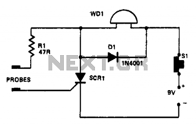
In this circuit, a warning device (WD1) is connected in series with a silicon-controlled rectifier (SCR1). When the liquid level creates a conductive path between the probes, the SCR becomes conductive, activating the warning device. The warning device can...

Three power levels are provided by the two logic inputs of this enhanced circuit. R5, D4, D5, and O2 create a power supply for the logic integrated circuit. These components can be excluded if an alternative low voltage source...

IC4 serves as a counter and oscillator combination, which is the pivotal component of the circuit. The oscillator generates an AC signal that is output on pin 7. This signal is routed through a voltage divider composed of resistors...
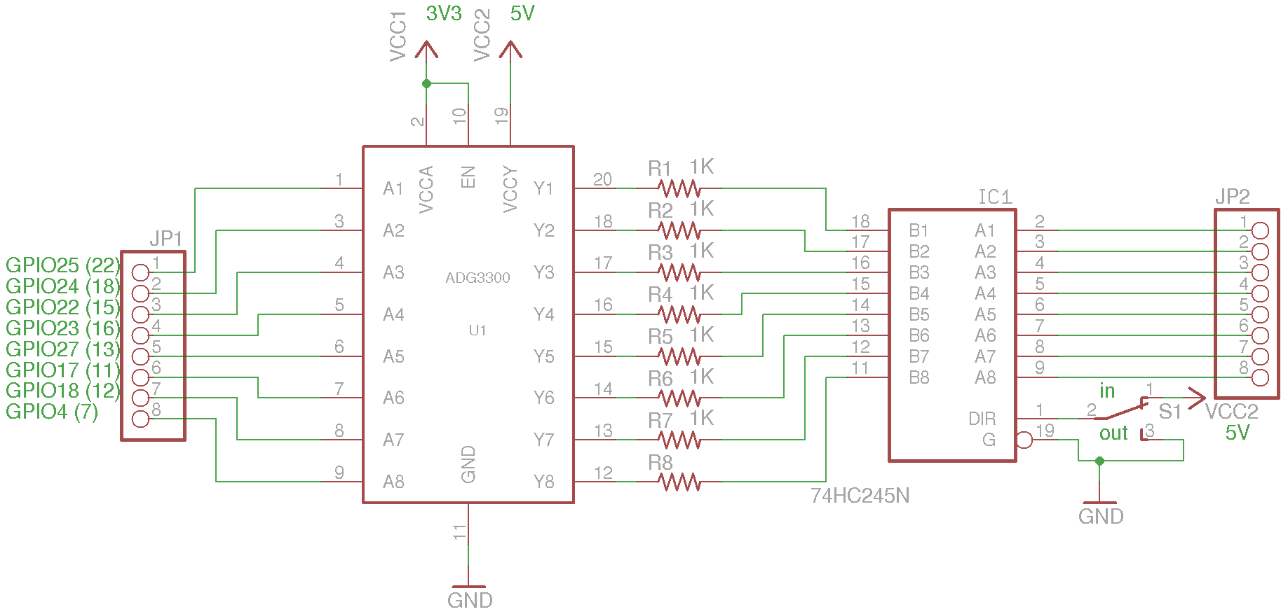
The current sourcing and sinking capability of the I/O pins on the Raspberry Pi is limited. According to the Wiki page, the current limit for each I/O block (for example, GPIO0 through GPIO27 combined) is only 26 mA maximum,...
There is no prior experience in building controllers, and there is uncertainty about how to begin. A budget constraint of less than 100 euros is present. A power thyristor is already available. The inquiry revolves around the best method...
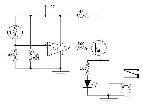
This circuit is designed to indicate when a plant requires watering. An LED flashes at a low frequency when the soil in the flower pot is excessively dry, and it turns off as the moisture level rises. The sensitivity...