
Water quality checker project simple circuit diagram

The water purity checker circuit utilizes an LDR, which changes its resistance based on the light intensity that passes through the water. When water is clear, more light reaches the LDR, resulting in lower resistance. Conversely, as the water becomes increasingly contaminated, the turbidity increases, reducing the amount of light that reaches the LDR and causing its resistance to rise. This change in resistance can be converted into a voltage signal using a voltage divider circuit, which can then be monitored by a microcontroller or a simple comparator circuit.
To implement this project, the circuit typically includes a power supply, the LDR, a resistor for the voltage divider, a comparator (such as an operational amplifier), and a piezo buzzer for the alert sound. The comparator is set up to trigger when the voltage from the LDR exceeds a predetermined threshold, indicating poor water quality. When this condition is met, the comparator output activates the piezo buzzer, providing an audible alert.
For practical applications, the circuit can be housed in a waterproof enclosure to ensure durability and reliability in a wet environment. Calibration may be necessary to adjust the threshold according to specific water quality standards. The integration with a water tank level controller can enhance the functionality, allowing for simultaneous monitoring of both water purity and level, making it a comprehensive solution for water management in domestic settings. This project not only serves as a useful tool for ensuring water quality but also provides an educational opportunity for understanding basic electronics and environmental monitoring.How to measure water purity How to test water quality using a simple electronics project You can perform water purity measurement and water quality analysis using this water purity checker circuit. This circuit is built around a simple LDR (Light Depended Resistor) and some discrete components. The most attractive feature of our water purity tes ter is that it gives a beep sound when the water purity level goes below a threshold value. You can implement this simple electronic project in your domestic water tank for water quality monitoring and testing. The detailed circuit diagram and constructional details of water quality testing device are given in this article.
Also you can integrate this with our previous circuit of water tank level controller, the resulting circuit will be an advanced engineering project. When the amount of mud in the water reservoir exceeds a threshold value, our water quality testing equipment starts producing a beep sound to alert us that the quantity of mud in the water has increased and needs a cleaning.
🔗 External reference
Related Circuits
It is the essential continuity of circuits Sel 8 Sources and Up/Down Sel 8 Sources, but can work and autonomously, collaborating with any suitable circuit of control. The Relay 1-8 can be 6-24v DC. For current of collector of...
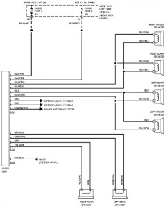
The following document provides a comprehensive car wiring diagram for the 1994 Mazda 626. It includes diagrams for the 2.0L and 2.5L engine configurations, covering the A/C circuit, heater circuit, anti-lock brake circuits, and anti-theft circuit. The wiring schematic for...
The amp was called "El Cheapo 2-30", and was rated at a maximum of 30W per channel into 16 Ohms. It used a single regulated power supply and capacitor coupled speaker. Having a scan of the original, the exact circuit...
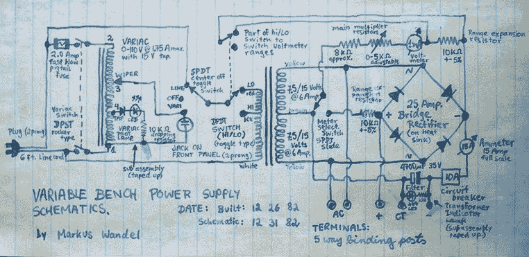
This power supply is able to deliver adjustable center-tapped DC from 0 to about 30 volts, as well as AC directly from the Variac and from the main transformer before the rectifier. What's primitive by today's standard is that...
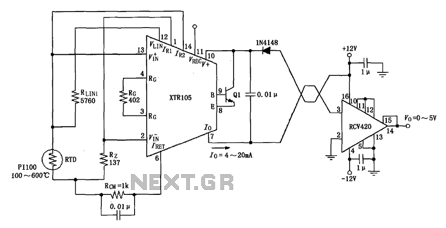
The circuit utilizes a Pt100 type resistance temperature detector (RTD). It operates within a temperature range of 100 to 600 °C, where the XTR105 outputs a current of 4 to 20 mA, and the RCV420 provides an output voltage...
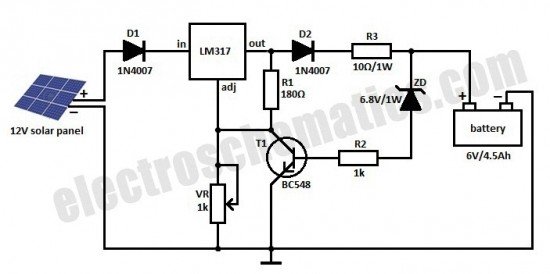
This is a solar charger circuit designed to charge Lead Acid or Ni-Cd batteries using solar energy. The circuit captures solar energy to charge the batteries. The solar charger circuit typically consists of several key components, including a solar panel,...