
Mazda 626 1994 Wiring Diagram
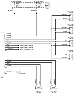
The wiring schematic for the 1994 Mazda 626 serves as an essential resource for understanding the vehicle's electrical system. The diagrams illustrate the interconnections between various components, allowing for effective troubleshooting and repair.
The 2.0L engine wiring diagram includes the layout for critical systems such as the air conditioning (A/C) circuit and heater circuit. The A/C circuit encompasses the compressor, condenser, evaporator, and associated relays and switches, providing a detailed view of the refrigerant flow and electrical control.
The heater circuit diagram outlines the connections for the heater core, blower motor, and temperature control switches, ensuring proper operation of the vehicle's heating system.
For the 2.5L engine configuration, the wiring diagram similarly details the A/C circuit, providing insight into the additional components that may be present due to the increased engine size.
The anti-lock brake system (ABS) circuit is crucial for vehicle safety, and the schematic includes the connections for the wheel speed sensors, ABS control module, and hydraulic control unit, helping to ensure the proper functioning of the braking system under various conditions.
Additionally, the anti-theft circuit is represented, detailing the components involved in securing the vehicle against unauthorized access. This includes the alarm system, immobilizer, and any related sensors.
Overall, the comprehensive wiring diagrams for the 1994 Mazda 626 facilitate a deeper understanding of the vehicle's electrical architecture, enabling technicians and DIY enthusiasts to perform maintenance and repairs with confidence.The following document is very complete car wiring of Mazda 626 year 1994. Here the diagrams which is contained in Mazda 626 car wiring diagram: 2.0L, A/C Circuit Heater Circuit 2.5L, A/C Circuit Anti-lock Brake Circuits Anti-theft Circuit.. 🔗 External reference
Related Circuits
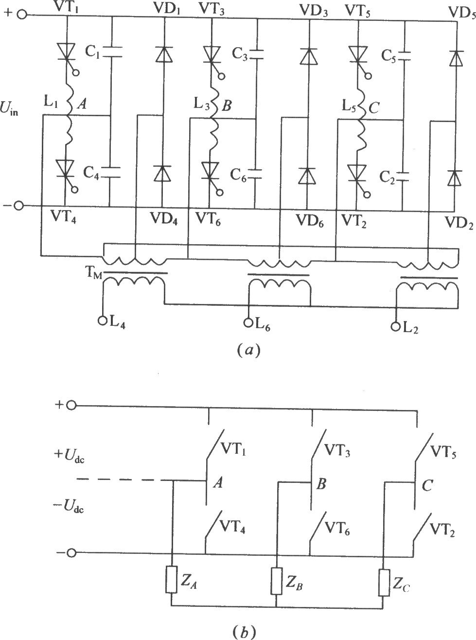
The figure illustrates a traditional three-phase bridge inverter circuit. Components VT1 to VT6 represent thyristors, while L1 to L6 are commutation reactors. Capacitors C1 to C6 serve as commutating capacitors, and the thyristor shut-off circuit is composed of two...
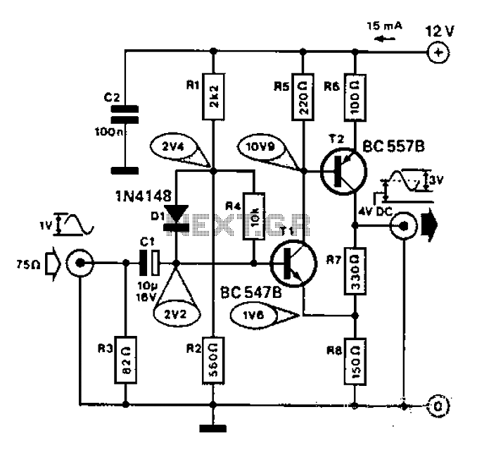
Commonly used for cameras or computers with black and white television connections, the amplifier has a gain of 3 and a bandwidth of 10 MHz. The described circuit is an amplifier designed for applications involving cameras or computers that interface...
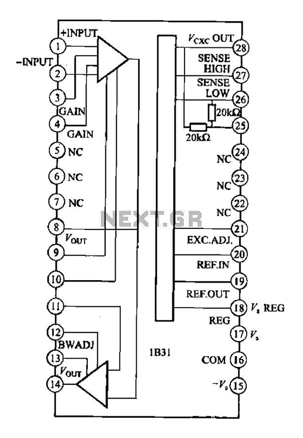
The Analog Devices 1831 is designed for strain gauge signal conditioning applications. It features an internal low drift input of 0.25V with a gain of 1000, exhibiting excellent linearity with a maximum deviation of 0.005%. The IC operates with...
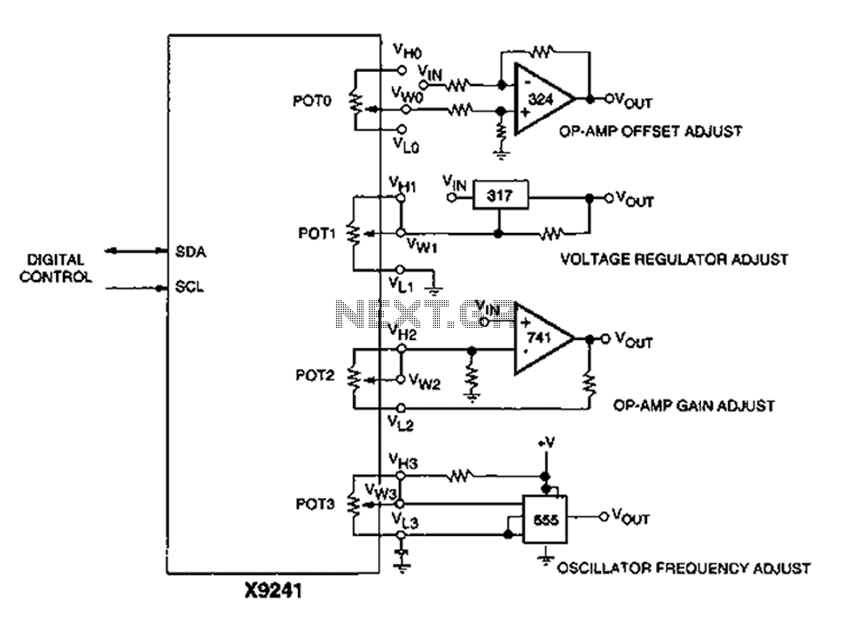
A XICOR X9241 POT IC module can be utilized to modify the four digital analog circuits, as depicted in the schematic. The XICOR X9241 is a digital potentiometer integrated circuit designed for precise adjustment of analog signal levels in various...
As shown in the figure, the 555 timer, resistors R1, RP1, and capacitor C1 form a controlled audio oscillator. The frequency of the oscillator is given by the formula f = 1.44 / ((R1 + 2 * RP1) *...
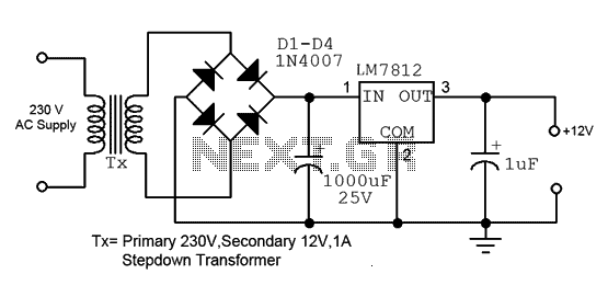
This is a straightforward 12V power supply circuit diagram. It features a fixed voltage output and is based on the LM7812 voltage regulator integrated circuit. The 12V power supply circuit utilizing the LM7812 voltage regulator is designed to provide a...