
Waveform generator II

The circuit design employs a CA3060 triple OTA, which is known for its versatility in analog signal processing. The two OTAs configured as switched current generators allow for precise control over the current levels, enabling dynamic adjustments in response to varying input conditions. The third OTA acts as a control element, ensuring that the output from the current generators is accurately managed.
The CA3160 BiMOS operational amplifier is utilized as a voltage follower, a configuration that provides high input impedance and low output impedance. This is particularly beneficial for buffering the 0.0022 µF integrating capacitor, which plays a critical role in timing applications. The integration capacitor is essential for creating time delays and shaping the output waveform, making it a key component in achieving the circuit's specified timing range of 20 µs to 20 seconds.
The adjustment range of 1,000,000:1 indicates the circuit's ability to finely tune the output characteristics, which can be particularly useful in applications requiring high precision. This range allows for significant flexibility in operation, accommodating various signal levels and conditions.
The inclusion of an "ON-OFF" switch that activates an LED serves practical functions beyond mere indication. The LED not only provides visual feedback for the user but also acts as a low-battery indicator, alerting the user to potential power supply issues. By dropping the battery voltage by approximately 1.2 volts, the LED effectively reduces the overall power consumption of the circuit. This design consideration is crucial for extending battery life, especially in portable applications where power efficiency is paramount. The reduction in supply current achieved through this method contributes to the longevity of the battery, making the circuit suitable for extended use in field applications.The circuit uses a CA3060 triple OTA (two units serve as switched current generators controlled by a third amplifier). A CA3160 BiMOS op amp serves as a voltage follower to buffer the 0.0022 µ¥ integrating capacitor. The circuit has an adjustment range of 1,000,000:1 and a timing range of 20 µ& to 20 sec. The "ON-OFF" switch actuates an LED that serves as both a pilot light and a low-battery indicator. The LED extends battery life, since it drops battery voltage to the circuit by approximately 1.2 volts, thus reducing supply current.
Related Circuits
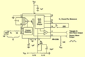
For measurement purposes in the electronics laboratory, signals of various frequencies and waveforms are frequently required. A standard function generator typically provides sine, triangular, and square wave outputs. The frequency must be adjustable and should encompass at least the...
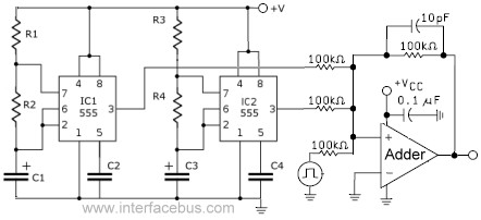
This circuit combines the outputs from two distinct 555 multivibrators using a summing operational amplifier (Op Amp). It serves to illustrate an alternative implementation of a 555 timer, with most background calculations addressed in other sections. The standard configuration...
The spark gap in the initial design consisted of copper wires bent into a ring at the end to suppress corona discharge. The current design is more advanced, utilizing spherical electrodes. This setup generates a 300 kV output pulse...
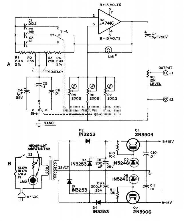
This high-quality, low-cost generator operates within a frequency range of 20 Hz to 20 kHz across three bands, maintaining less than 1% distortion. It utilizes LM1-10 V at 14 mA (344,1869, 914) or 10 V at 10 mA (913,...
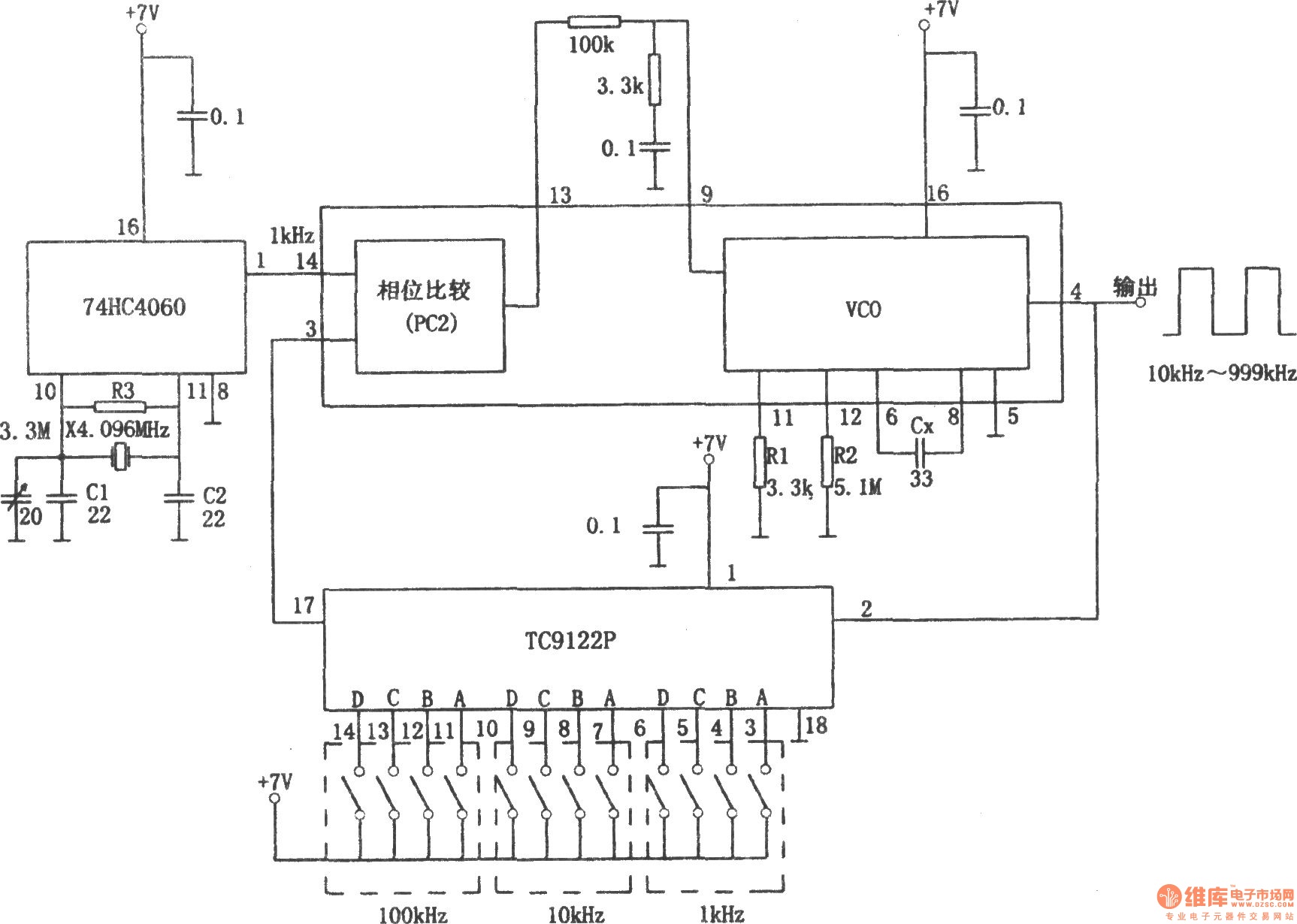
The PLL pulse generator is illustrated in the accompanying chart. The circuit represents a phase-locked loop (PLL) pulse generator. The PLL generates a fractional frequency from a crystal oscillator, producing a 1 kHz stepped frequency signal. Additionally, it outputs...

Noise level measured into 75ohm 3.1kHz BW using Siemens D2006 level meter: -80dBU (77.5mV) from zero to 1MHz and drops 3dB on 17MHz. Decrease the first coupling capacitor (68nF) to 10nF to increase the lower limit to 50kHz. The...