
Wet/Dry Mix Knob - will this schematic work

To implement a wet/dry knob for parallel compression on a GSSL (Chameleon Labs 7720), the circuit can be designed using a potentiometer to blend the processed signal with the dry (unprocessed) signal. The wet/dry control allows for real-time adjustment of the ratio between the compressed and uncompressed signals, providing flexibility in the mixing process.
The typical configuration includes a dual-gang potentiometer, where one section controls the wet signal and the other controls the dry signal. The potentiometer's wiper connects to the output of the compressor, while the other end connects to the unprocessed signal path. The two signals are then fed into a summing amplifier or directly into the output stage of the circuit.
In the schematic, the wet signal path should include any necessary components such as capacitors for coupling and resistors for impedance matching. It is essential to ensure that the levels of both signals are balanced to avoid distortion or loss of fidelity. The output of the summing stage can then be routed to the main output of the unit.
Additionally, care should be taken to maintain the integrity of the original signal path, ensuring that the addition of the wet/dry knob does not introduce unwanted noise or interference. Proper grounding and shielding techniques should be employed to minimize these issues.
Overall, the implementation of a wet/dry knob in the GSSL for parallel compression enhances the versatility of the audio processing, allowing for creative control over the final sound output.Hi I am looking to add a simple wet/dry knob to a gssl (actually chameleon labs 7720) for parallel compression. Came across this schematic - it seems.. 🔗 External reference
Related Circuits
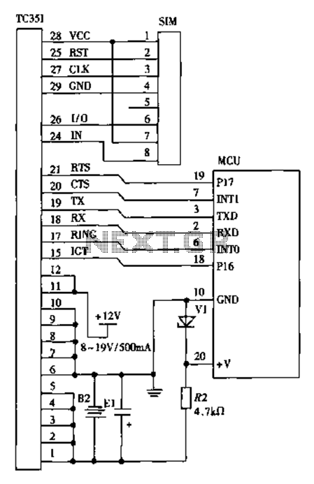
The design of a wireless data communication circuit is primarily intended for motor vehicles and fixed base station systems to facilitate close-range wireless data exchange. The circuit is based on the core chip nRF401 and its associated components. The...
TX OpAmps TX Mixer (QSE) PTT RX Switching PA/Filters External Connections Comments Revisions WB5RVZ SDR Home. This stage integrates the TX Mixer into the board, allowing for the modulation of the Dividers' output signals by the four I and...
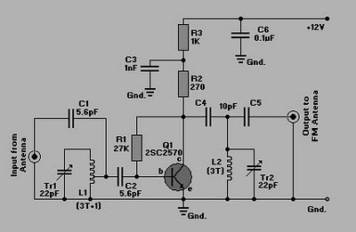
This is a simple circuit of an FM booster designed to enhance the reception of programs from distant FM stations. The amplifier effectively captures signals from far-off FM stations. The configuration is set up as a common-emitter tuned RF...
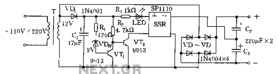
The circuit is automatically converted to a low-voltage configuration. A 220V AC supply is stepped down by transformer T. After this, the breakdown voltage of diode VDw causes transistors VT1 and VT2 to turn off, resulting in the solid-state...
This chapter provides detailed schematics of various power supplies suitable for use with common Ar/Kr ion tubes available to hobbyists in the surplus market. Included are examples of commercial designs (Omnichrome 150R and 532 head, Lexel 88 and head)...
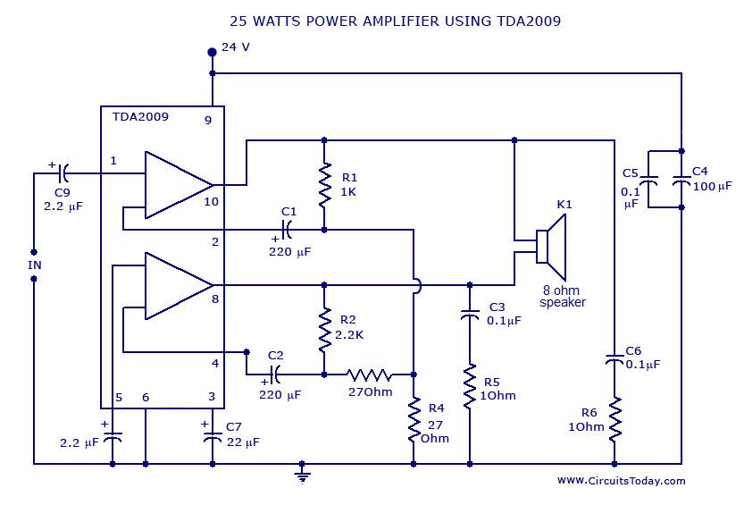
Power amplifier circuit diagram with schematics. This simple audio power amplifier circuit is designed for 25 watts output power using TDA 2009 IC, which has two channels (stereo), 12.5 W for each channel. The described power amplifier circuit utilizes the...