
RXTX V6.3 TX Mixer

For example, when operating on the 40m band with an SDR center frequency of 7.056 MHz, if the SDR is tuned to a CW station at 7.066 MHz (10 kHz above the center frequency), the I and Q signals from the RX hardware can be monitored through an amplifier or headphones. In a noise-free environment, a single 10 kHz CW signal would be heard on both channels, with one channel being 90 degrees out of phase with the other. The SDR RX software analyzes the phase difference between the I/Q signals to determine that the signal is 10 kHz above the center frequency, displaying it as a broken line on the waterfall. The software then frequency shifts this signal at the soundcard output to produce a normal CW tone from the speakers.
When transmitting at the cursor's frequency (7.066 MHz), the SDR software generates a 10 kHz signal (the difference between the center frequency and the selected TX frequency) in both I and Q outputs, again in quadrature. This signal is sent to the SDR hardware on the TX side, through the OpAmps, and into the mixer, where it interacts with the local oscillator (LO) frequency of 7.056 MHz. The input to the mixer is the 10 kHz signal from the soundcard, and the output is the RF product of the LO and the input 10 kHz signal. Listening to the input 10 kHz signal reveals a tone, which is audible due to its representation of the frequency difference between the center frequency and the desired transmit frequency. Selecting a higher transmission frequency, such as 7.080 MHz, results in a 24 kHz signal that may not be audible.
The TX OpAmps operate at unity gain, splitting the incoming I and Q signals into four components: 0°, 180°, 90°, and 270° phase. Each of these components is input to the mixer, which is switched by LO signals that are 90 degrees apart in phase. The mixer produces two outputs that are the up-converted RF products, which are 180 degrees out of phase. These outputs are fed to the Power Amplifier Filter (PAF) and its input transformer. The PAF Input Transformer, T200, cancels one of the anti-phased RF signals based on which is leading or lagging, similar to the RX process where minor phase errors are compensated. The SDR software adjusts the phase and amplitude of the I/Q signals to ensure that the mixing product 10 kHz below 7.056 MHz is cancelled, leaving a signal 10 kHz above 7.056 MHz at the PAF Input Transformer output. The SDR software transmits two appropriately phased signals from the soundcard; however, it is not the tone that is transmitted, but an up-converted RF product that is amplified and filtered in the PAF board.TX OpAmps TX Mixer (QSE) PTT RX Switching PA/Filters External Connectons Comments Revisions WB5RVZ SDR Home This stage adds the TX Mixer to the board and provides the modulation of the Dividers` output signals by the 4 I and Q signals from the OpAmps. The result is a double sideband RF waveform that will be coupled into the PA stag e. Let`s suppose you were working 40m with a SDR center frequency of 7. 056 MHz. You have tuned your SDR (via the software) so that you are listening to a CW station on 7. 066 MHz (10 kHz up from the center frequency). If you were to listen to the I and Q signals from the hardware RX via an amplifier or headphones (assuming there were no other signals and little noise) you would hear a single 10 kHz CW signal on both channels. Your ears may or may not be able to detect the fact that the tone in one ear is 90 degrees out of phase (I.
e. , In quadrature) with the tone in the other ear. By comparing the phase difference between the I/Q signals the SDR RX software determines that this signal is 10KHz higher than the center frequency and displays the CW signal as a broken line on the waterfall. It also frequency shifts this signal at the output of the soundcard so it is heard at as normal CW tone from the speakers.
Now, assume you decide to transmit on that frequency where you have placed your cursor (7. 066 MHz). Your SDR software will emit a 10 kHz signal (the delta between the center frequency and the selected TX frequency) in both the I and Q outputs, again, in quadrature. This will go into the SDR hardware on the TX side, through the OpAmps and into the mixer, where it will beat up against the LO center frequency of 7.
056 MHz. The input to the mixer is 10KHz from the soundcard; the output from the mixer is the RF product of the LO and the input 10 kHz signal. If you were to listen to the input 10 kHz signal you would hear a tone. This tone is audible simply because it represents the delta between the center frequency and the desired transmit frequency, in this case, only 10 kHz, and, since it is in the range of audio frequencies, is audible.
If you were to select a higher frequency on whch to transmit, sat 7. 080 MHz, the resultant signal would be a 24 kHz signal; perhaps your dog would hear it, but you certainly would not! The TX OpAmps are unity gain and serve to split the incoming I and Q signals into 4 components: 0, 180, 90, and 270 degree phase.
Each of the four are then input to the Mixer and are switched ("mixed" by the LO signals which are 90 degrees apart in phase). The two outputs of the mixer are the up-converted RF products, in anti-phase (I. e. , 180 degrees apart). These are fed to the PAF and its input transformer. The PAF Input Transformer, T200, will cancel out one or the other of the anti-phased RF signals out, depending upon which is leading and which is lagging.
This is just like the RX, any minor phase errors are compensated. The software will make the phase and level of the I/Q signals such that the mixing product 10KHz below 7. 056 is cancelled leaving a signal 10KHz above 7. 056 at the output of the PAF Input Transformer. The SDR software sends two suitably phased signals from the soundcard it is not that tone that is transmitted, but an up-converted mixer RF product, amplified and filtered in the PAF board.
🔗 External reference
Related Circuits
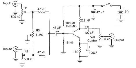
This audio mixer circuit diagram electronic project is designed using a few common electronic components. The audio mixer circuit project has two input channels. The input signal can be independently controlled using the R1 and R2 variable resistors. The...
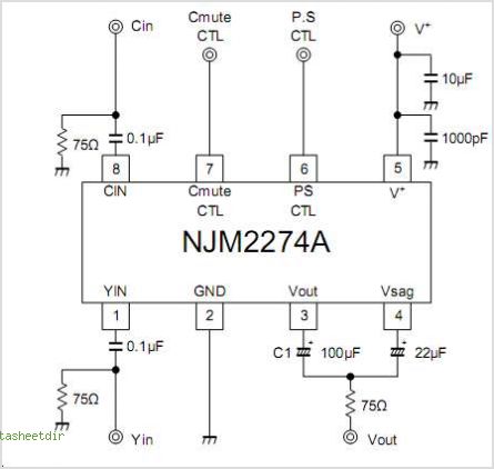
The NJM2574 is a low voltage video amplifier that includes a low-pass filter (LPF) circuit, a driver, and an internal clamp/bias function. It is designed to connect directly to a TV monitor using a composite input signal of 0.5V...
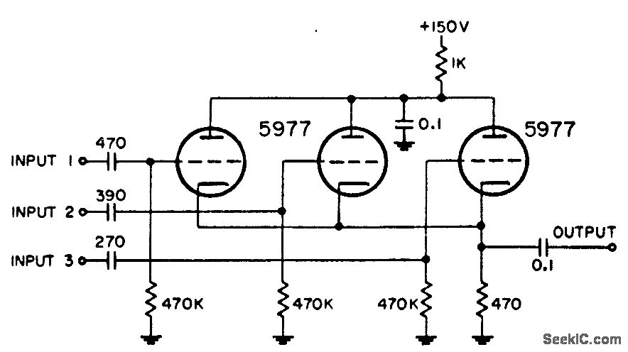
Utilized in radar systems for the integration of any three of the following components: radar video, beacon, range markers, range strobe, and azimuth markers. -NBS, "Handbook Preferred Circuits Navy Aeronautical Electronic Equipment," Vol. 1, Electron Tube Circuits, 1963, p...
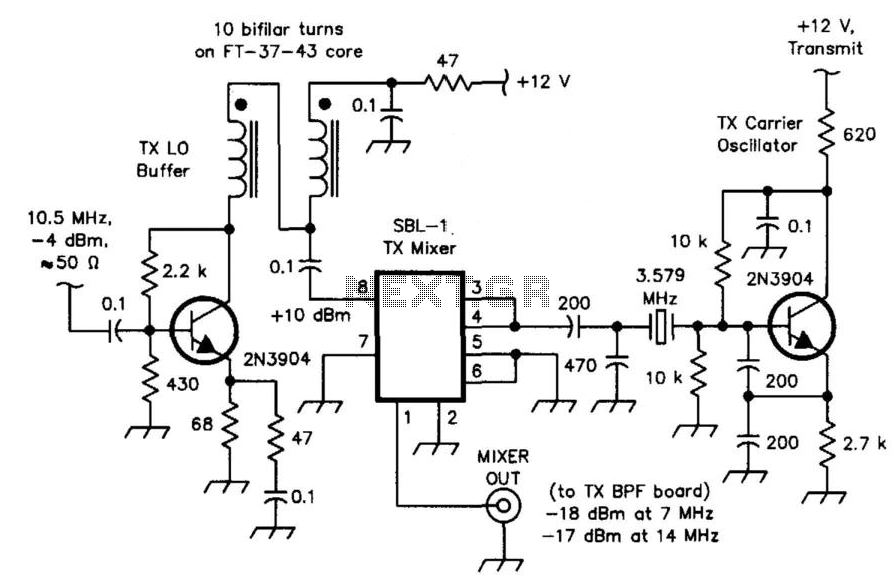
The transceiver mixer and carrier oscillator in the band-imaging (7- and 14-MHz) CW transceiver. Careful selection of drive levels and the use of a spectrally clean carrier oscillator ensure low spurious-signal content in the transmitter output. This transceiver mixer...
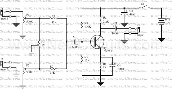
This is a classic signal mixer that is used for audio purpose. VR1 & VR2 are inputs audio volume controllers and VR3 is used to control the balance between Input1 and Input2. Connect a dynamic microphone to Input1 and...
The AN12974A Audio Power Amplifier features built-in Automatic Gain Control (AGC) circuitry and Spatializer technology. Spatializer is an exclusive signal processing technology from Desper Products, Inc. that generates surround sound for low-power mobile applications. This technology is based on...