
Whats the purpose of the diodes in this circuit

The headlight wiring circuit in a vehicle typically utilizes diodes to manage the electrical pathways and prevent back-feed between different components. In this particular setup, the two diodes play a critical role in ensuring that the light relays function correctly, regardless of which switch is active. Each diode is positioned to allow current to flow in one direction while blocking it in the opposite direction, effectively isolating the circuits controlled by the light switch and the high beam flasher.
If the diodes were removed and replaced with straight links, several issues could arise. Without the diodes, there would be a risk of back-feeding current into the inactive switch, potentially causing both circuits to engage simultaneously. This could lead to unexpected behaviors such as both the low beams and high beams being illuminated at the same time, which could overwhelm the circuit and lead to component failure or reduced lifespan of the bulbs.
Moreover, if neither switch is activated, the absence of diodes could create a situation where the circuit remains open, leading to uncertainty in the system's behavior. The diodes ensure that when one switch is active, the other remains isolated, preventing any interference that could result from simultaneous activation. In summary, the diodes are essential for maintaining the integrity of the headlight control system, ensuring that each function operates independently and efficiently while preventing potential damage from unintended current pathways.Get my head around the headlight wiring in my car, and I`m curious what purpose the two diodes in this diagram serve. Hoping one of the clever people on here can explain it for me: Wow - thanks for editing my post and the very quick replies.
Fantastic. I understand at a high level what the circuit is doing and that there`s the two in dependent ways of activating the light relays - through the light switch or when flashing the high beams - but I guess what my real question is - specifically what are the diodes doing, to ask it this way - if you removed the diodes from the circuit and replaced with straight links what would go wrong madz Jul 16 `12 at 12:40 Appreciate the replies. What I`m struggling with when I look at this diagram is that if either switch is not switched to a position to activate high beam, it appears the terminal is open circuited - so would be isolated anyway wouldnt it (without the need for the diode which is now only connected on one end anyway) And if the switch is closed then the connected diode will conduct as it is oriented almost the wrong way around to be isolating the switch Or am I misunderstanding I was wondering whether the diodes were perhaps more to do with controlling current flow when BOTH switches were on madz Jul 16 `12 at 21:58
🔗 External reference
Related Circuits

This alarm system utilizes a loud police siren to deter potential intruders. Activated by a single clap, the circuit triggers the alarm for three minutes, which is adequate to alert nearby residents. The design incorporates a sensitive clap switch...
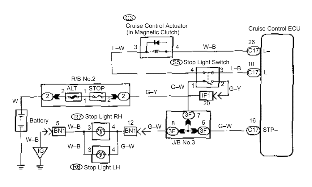
When the brake pedal is depressed, battery positive voltage normally applies through the STOP fuse and stop light switch to terminal STP of the ECU, and the ECU turns the cruise control off. A failsafe function is provided so...
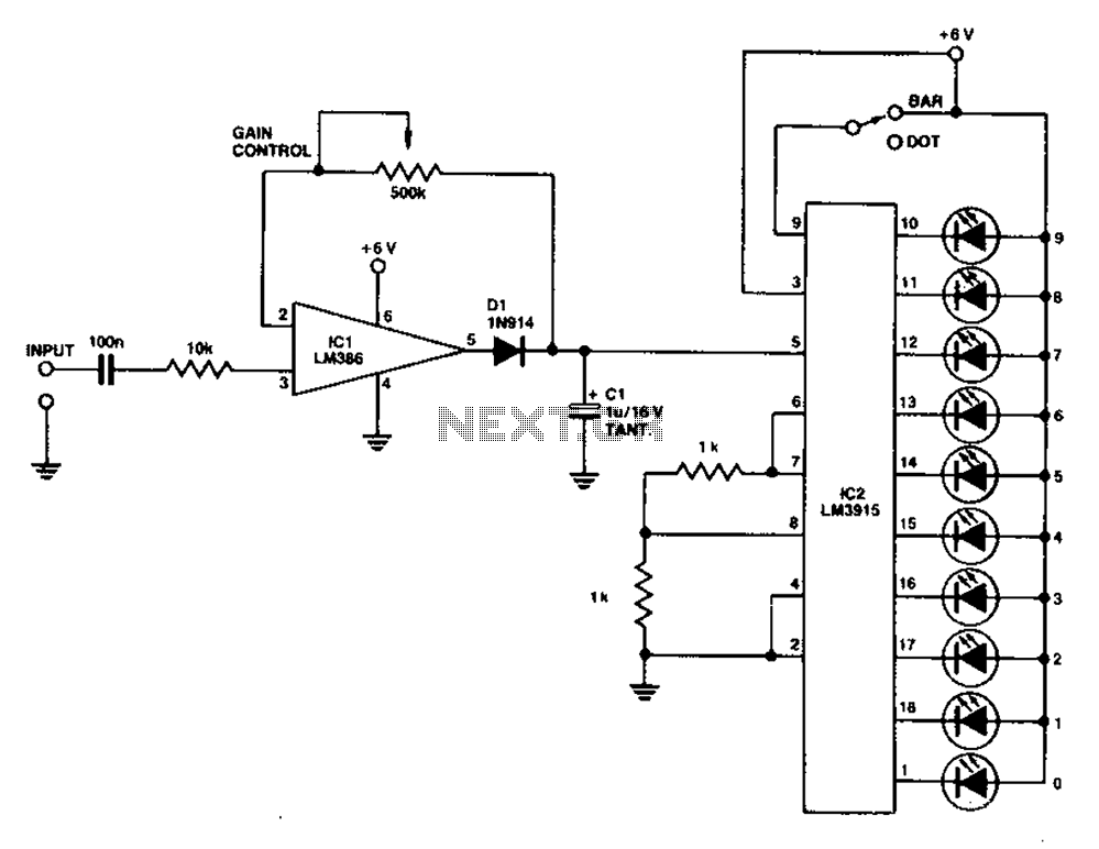
A simple level power meter designed to provide a high-fidelity sound system with a bar or dot matrix display. The green LED display indicates levels from 0 to 7; level 8 is shown in yellow, and level 9 is...
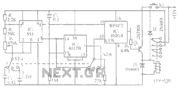
The system operates between 10 minutes to 2 hours, featuring a 100-line bell controlled by a multi-gear stick labeled S2 41f. The integrated circuit (IC) functions as a self-excited multivibrator. The device can manage binary pulses ranging from 3...
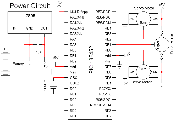
The Olimex P-40 development board will be utilized, though the circuit can also be constructed on a breadboard due to its simplicity. The schematic for the initial implementation of servo control is provided below. Servos, like any motors, can...
This flash circuit is a typical camera flash. This flash circuit functions as a high-voltage power supply for camera flash units, enabling the rapid discharge of energy to produce a bright flash of light. The primary components of a typical...