
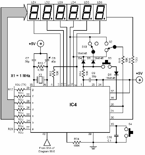
LED strip meter circuit diagram of a point

The described power meter circuit is an essential tool for audio engineers and enthusiasts aiming to monitor audio levels accurately in high-fidelity sound systems. The primary function of the circuit is to visually represent the audio signal levels through a series of LED indicators. The green LEDs signify normal operating levels from 0 to 7, providing a clear and immediate visual feedback to the user. When the audio level reaches 8, the yellow LED activates to indicate a cautionary level, while the red LED at level 9 signals peak power, alerting the user to potential distortion or clipping in the audio output.
In terms of operation, the circuit incorporates a gain control feature that allows for calibration based on the specific characteristics of the audio device being used. This feature is crucial for ensuring that the meter provides accurate readings across different equipment, enabling users to maintain optimal sound quality.
The power requirements of the circuit are significant, with a current draw of 200mA. This level of consumption suggests that a stable external power supply is necessary to ensure consistent performance. Using a battery may lead to inadequate power delivery, resulting in unreliable operation or premature battery depletion. Therefore, a suitable power supply should be selected to meet the current and voltage specifications required by the circuit.
Overall, this simple level power meter circuit is an effective solution for monitoring audio levels, enhancing the user experience in high-fidelity sound applications. Its design considerations, including visual indicators, gain control, and power supply requirements, contribute to its functionality and reliability in professional audio settings.A simple level power meter to provide high-fidelity sound system bar or dot matrix display. Green LED display 0-7; 8 show yellow, red 9, the LED displays peak power. This circu it provides gain control for device calibration. Because this element absorbs 200mA, recommended power supply instead of the battery to run the device.
Related Circuits
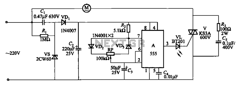
The circuit depicted in Figure 3-8 is designed to control a fan, allowing it to gradually decrease its airflow until it stops completely. This process is repeated in cycles. The circuit utilizes a 555 integrated circuit (IC) configured as...
The figure illustrates an NE555 frequency modulation (FM) circuit. In this circuit, pin 7 of the NE555 is connected to an FM modulation section that consists of resistor R5 and capacitor C2, although the frequency range is somewhat limited....
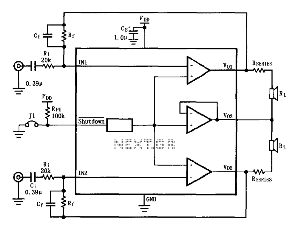
The circuit for the LM4910 is designed to minimize output noise and reduce power consumption. The output noise is attenuated by utilizing a resistor in series with the load. A feedback resistor Rf is used in conjunction with a...
A digital audio frequency (AF) counter can be constructed using a minimal number of components by employing a single 7226B integrated circuit (IC) from Intensil, as depicted in the accompanying diagram. This circuit has an upper frequency limit of...
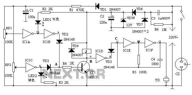
The alarm protection can trigger a sound and light alert when the mains voltage exceeds or falls below a predetermined threshold. It automatically disconnects the electrical power supply without damaging the electrical protection. The device is compact, fully featured,...
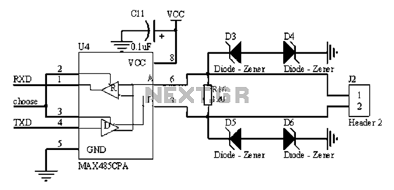
The RS485 bus is a widely used serial bus standard that employs balanced differential transmission and reception techniques, enabling it to effectively suppress common mode interference. It is particularly advantageous for communication distances ranging from tens of meters to...