
Wheelchair Obstacle Avoidance System

The process of programming an Arduino microcontroller involves several key steps to ensure successful interaction between the hardware and software components. Initially, it is crucial to obtain the correct version of the Arduino Integrated Development Environment (IDE), which can be downloaded from the official Arduino website. The latest version is recommended to ensure compatibility with the newest features and libraries.
Once the IDE is installed, users should download the relevant Arduino sketches, which contain the source code necessary for the desired functionality of the project. These sketches can be opened within the IDE, allowing for code inspection and modification if needed.
The next step involves assembling the circuit as per the project requirements. This typically includes connecting various components such as sensors, actuators, and other electronic devices to the Arduino board. Proper attention must be given to the wiring to ensure that all connections are secure and correctly oriented.
After the circuit is complete, the Arduino microcontroller must be connected to a computer via a USB cable. Within the IDE, users need to select the appropriate board type and serial port to establish communication between the IDE and the Arduino. This is accomplished through the Tools menu, where users can navigate to the 'Boards' and 'Serial Port' options to make the necessary selections.
With the system set up, the user can initiate the upload of the program to the Arduino by clicking the upload button in the IDE. This process compiles the code and transfers it to the microcontroller. If any issues arise during this process, error messages will be displayed in the console window, providing insights into potential problems. It is essential to review these messages to diagnose any errors related to the code or circuit setup.
In the event of errors, users are advised to carefully check their circuit connections and review the code for logical or syntax errors. Debugging may involve making adjustments to either the hardware or software components, followed by re-running the upload process to verify successful execution. This iterative approach is fundamental in embedded systems development, ensuring that the final implementation operates as intended.First of all, download any version of arduino software ( new version is better) using the link given above and then download the provided arduino sketches. Once download is complete, open the sketches and you will be able to see the written codes. Complete the circuit and connect the arduino micro-controller to computer. Select the right arduino board and serial port by going inside tools menu > boards and serial port. Once you connect arduino to computer, click on upload button to upload the program to arduino micro-controller. Errors will be displayed in the console window, if any errors are found. Check the circuit and debug the program and run it again if there are any errors. 🔗 External reference
Related Circuits
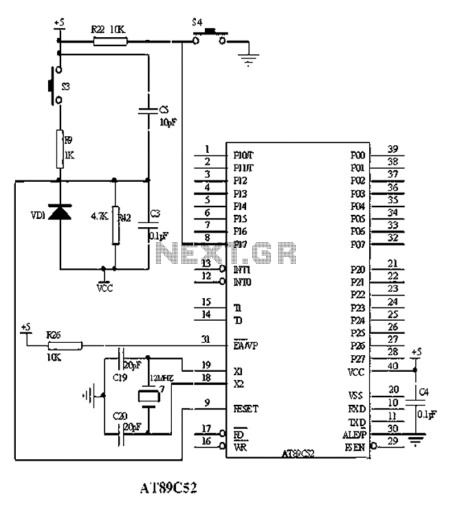
The American Atmel AT89C52 is a low-voltage, high-performance CMOS 8-bit microcontroller chip that contains 8KB of rewritable program memory and 256B of random access data memory (RAM). Atmel's high-density devices utilize non-volatile memory technology and are compatible with the...
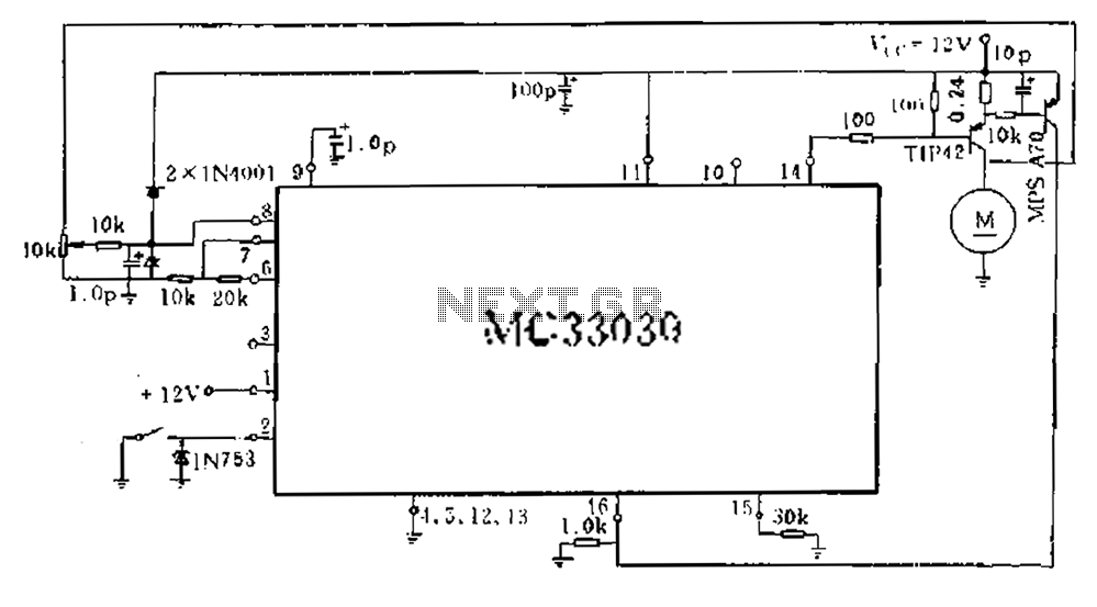
An alternative approach involves obtaining a motor's counter electromotive force from the motor end of the related signal after it has been amplified and averaged across three pins. The drive output A functions as a single-ended output, which controls...
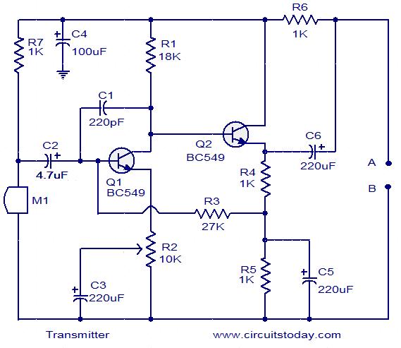
The circuit schematic illustrates a simple audio surveillance system in which the transmitter captures sound from one location, while the receiver reproduces it at another location. Both the transmitter and receiver are connected by a single wire, which carries...
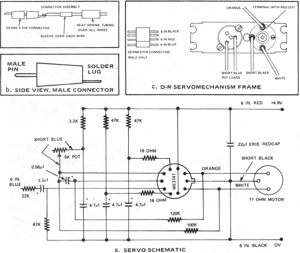
Part II of the AAM Commander RC System Article, scanned from the May 1972 edition of American Aircraft Modeler. The AAM Commander RC System is a sophisticated radio control system designed for model aircraft, providing enhanced control and performance for...
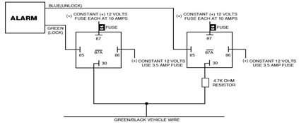
The following circuit illustrates the Ford Probe Single Wire Door Alarm System. This Single Door Locking Wire manages both LOCK and UNLOCK functions, indicating that the pulse wires must be connected to the same vehicle wire. The system primarily...
The TPA2011D1 is a 3.2-W high-efficiency, filter-free Class-D audio power amplifier housed in a 1.21 mm x 1.16 mm wafer chip scale package (WCSP) that requires only three external components. This amplifier features 95% efficiency, an 86-dB power supply...