
aam commander rc system

The AAM Commander RC System is a sophisticated radio control system designed for model aircraft, providing enhanced control and performance for hobbyists and enthusiasts. This system typically includes a transmitter, receiver, servos, and various electronic components that facilitate communication between the pilot and the model aircraft.
The transmitter serves as the control interface for the pilot, allowing for the manipulation of various control surfaces such as ailerons, elevators, and rudders. It operates on specific radio frequencies, ensuring reliable signal transmission to the receiver installed in the aircraft. The receiver, in turn, interprets the signals from the transmitter and translates them into mechanical movements through servos, which are responsible for adjusting the control surfaces accordingly.
In addition to the basic components, the AAM Commander RC System may incorporate features such as dual rates, which allow pilots to switch between different sensitivity settings for control inputs, and mixing capabilities that enable complex maneuvers by combining inputs from multiple channels. The system is designed to be user-friendly, ensuring that both novice and experienced pilots can operate their model aircraft with precision and ease.
The electronic schematic of the AAM Commander RC System would typically include the following key elements:
1. **Transmitter Circuit**: This section includes the oscillator circuit, modulation circuits, and power supply components that generate and transmit radio signals. The transmitter may utilize a microcontroller for signal processing and control logic.
2. **Receiver Circuit**: The receiver circuit includes an antenna, RF amplifier, demodulator, and servo output stage. The antenna captures the incoming radio signals, which are amplified and demodulated to extract the control information.
3. **Servo Control**: The servos are controlled by PWM (Pulse Width Modulation) signals generated by the receiver. The schematic would show the connection of the receiver output pins to the servo inputs, detailing the power supply and ground connections.
4. **Power Supply**: The power supply circuit is crucial for both the transmitter and receiver, ensuring that all components operate within their specified voltage and current ratings. It may include voltage regulators and filtering capacitors to stabilize the power supply.
5. **Antenna Design**: The schematic may also depict the design of the antenna used for both the transmitter and receiver, which is essential for achieving optimal range and minimizing interference.
Overall, the AAM Commander RC System represents a well-engineered solution for model aircraft control, showcasing the integration of various electronic components to enhance the flying experience.Part II of the AAM Commander RC System Article, scanned from the May 1972 edition of American Aircraft Modeler.. 🔗 External reference
Related Circuits
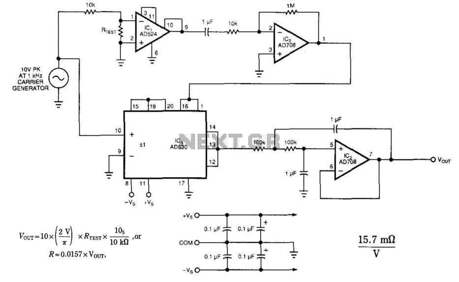
The circuit employs a synchronous detection method to measure low-level resistances. Other low-resistance measuring circuits may introduce excessively large currents into the system under test. This circuit synchronously demodulates the voltage drop across the system under test, allowing the...

The pressure transmitter circuit data acquisition system utilizes the 1B31, an 18-bit A/D converter (AD1170), and an MCS-51 microcontroller. The configuration, as depicted in the accompanying diagram, features a full-scale output voltage of 10 mV from the pressure transmitter...
The following file contains detailed information about the design of a basic clock oscillator circuit diagram. Included in this file is information about selecting the components. The clock oscillator circuit is a fundamental component in various electronic systems, providing a...
A newer version of this circuit board is available. Rev 4 includes a faster CPU, more memory, more I/O, and an optional LCD. It is recommended to use Rev 4 for new projects. Although the older board is no...

Continuous monitoring of brain activity is essential for understanding the neural substrates of various physiological and pathological brain functions. The low amplitude of EEG signals, which range from 1 to 500 µV and have a frequency of 1 to...
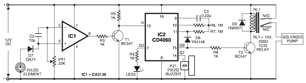
Pyroelectric Fire Alarm System Diagram. The front end of the circuit contains a sensitive signal amplifier constructed close to IC1 (CA3130). It delivers a high output when the temperature near the piezo component raises. IC CA3130 is a CMOS...