
Which only uses the 5V power supply connection circuit

The circuit operates by converting the error signal into a PWM output, which modulates the width of the pulses to control the power delivered to the load—in this case, a DC motor. The input error signal is derived from the differential position error, calculated based on the system's position feedback from the sensors located at 6 and 7 feet. This feedback is essential for maintaining the desired position of the motor.
The PWM signal is generated by comparing the error signal against a reference signal within a comparator circuit. The output of this comparator drives a power amplifier, which is responsible for supplying the necessary current to the motor. The operational amplifiers in the circuit play a critical role in signal conditioning and ensuring that the error signals are appropriately scaled and filtered. The first operational amplifier processes the error signal and applies damping to reduce oscillations and improve stability.
The gain and damping of the system are set using resistors RD and R, which form part of the feedback network in the operational amplifiers. By adjusting these resistors, the performance of the motor control system can be fine-tuned to achieve desired response characteristics, such as settling time and overshoot. This adjustment is crucial for applications requiring precise control over the motor's position and speed.
Overall, this circuit design emphasizes the importance of feedback control in motor applications, utilizing PWM for efficient power management and operational amplifiers for effective signal processing, ensuring robust performance in dynamic environments.Error processing segment is converted to a pulse width modulated (PWM) signal output from 3 feet (MC signal). Also calculate the differential position error, which represents t he small velocity, from 6 and 7 feet elected as a system with damping. A speed proportional to their positive and the other negative is proportional to the speed. Two signal into an analog channel in an external operational amplifier damping in number. With another damping operational amplifier and the position error signal as a synthesis may be an analog signal for controlling the power amplifier final stage, driving a DC motor. (See Fig. 13-17). Gain and damping by two resistors RD and R. systems to adjust, Tsui excellent performance of the system.
Related Circuits
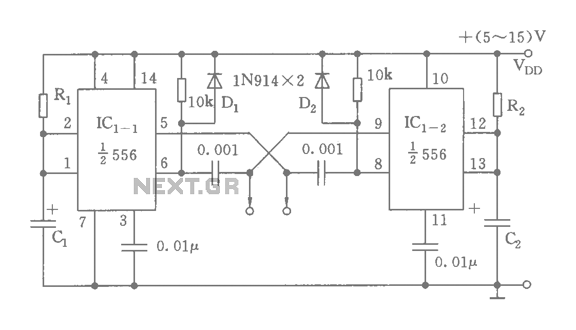
The circuit features a dual time base using a 556 timer, which comprises two synchronized multivibrators and two output clock signals. The output signals are synchronized with defined intervals, and the oscillation frequency can be adjusted by varying the...
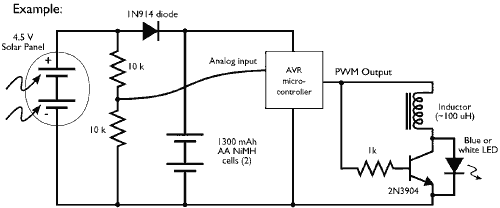
This example demonstrates the PWM (pulse-width modulation) output of a microcontroller controlling a Joule Thief style voltage booster to power a white LED. The circuit described utilizes a microcontroller to generate a PWM signal, which is an effective method for...
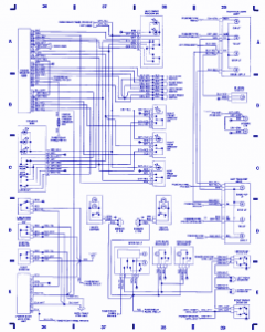
Emergency lights, fuse/relay panel, fresh air blower switch, engine control module, ignition coil, console switch, power windows, ABS control unit, ABS hydraulic unit, instrument cluster, taillight, headlight switch, automatic solenoid, ignition switch. The described circuit encompasses multiple essential components for...
In addition to its primary function as a headphone amplifier, the circuit is suitable for various applications requiring a wide bandwidth low power amplifier. It is constructed using an operational amplifier (op-amp), with its output current enhanced by a...
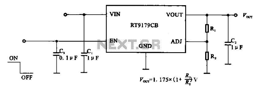
The RT9179CB is a power management chip utilized in power supply circuits. It serves as a linear regulator power management chip. This circuit is commonly employed in various products, such as computer motherboards, LCD monitors, and others. It is...
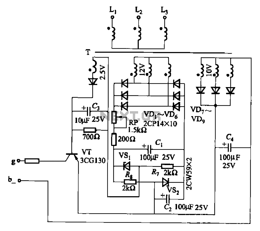
The CJ-12 Excitation Regulator is designed for automatic excitation control of small generators with a capacity of 250 kW or less. Its circuit is illustrated in Figure 7-45. The adjustment potentiometer RP allows for the modification of the measuring...