
Stereo Headphone Amplifier Circuit

The described circuit utilizes an operational amplifier as the core component, which is known for its high gain and ability to amplify low-level signals. The op-amp is configured in a non-inverting or inverting configuration, depending on the desired application. The circuit's design aims to provide a wide bandwidth, making it ideal for audio applications where fidelity and clarity are essential.
To enhance the output current capabilities of the op-amp, two transistors are employed. These transistors are typically configured in a push-pull arrangement, allowing the circuit to drive higher loads without distortion. This configuration also aids in improving the overall efficiency of the amplifier, as it can provide sufficient current to drive headphones or other low-impedance loads effectively.
The power supply for this circuit is usually a dual supply, providing both positive and negative voltages to the op-amp, ensuring that it can handle the full range of audio signals. Bypass capacitors are often included near the power supply pins of the op-amp to filter out noise and stabilize the power supply voltage, which is crucial for maintaining performance.
Input and output coupling capacitors may also be integrated into the design to block DC offsets while allowing AC signals to pass. This is particularly important in audio applications, where any DC component could lead to speaker damage or distortion.
Overall, this circuit design is versatile and can be adapted for various low-power amplification needs, making it a valuable addition to many electronic projects. Its simplicity and effectiveness in amplifying signals while maintaining a wide bandwidth make it an excellent choice for both hobbyists and professionals in the field of electronics.Apart from the obvious usage as a headphone amplifier, the circuit can be used for a range of applications where a wide bandwidth low power amplifier is needed. The circuit is based on an opamp, with its output current boosted by a pair of transistors.. 🔗 External reference
Related Circuits
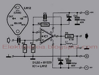
This is an 80W power amplifier OCL circuit that utilizes the integrated circuit LM12. It effectively enhances bass and treble performance. When connected to a CD player, it produces high-quality sound, especially when paired with a good pre-tone control....
This circuit is used to power an LED with a voltage of 230V. The 230V must be reduced to meet the LED's voltage requirements. To achieve this, a circuit is necessary as described below. The circuit designed to power an...
TV video signal processor circuit. The ECG1064 chip includes a primary video amplifier, two sync pulse amplifiers, a look-out protector, a noise detector, two noise gates, an automatic gain control (AGC) detector, an intermediate frequency (IF) AGC amplifier, a...
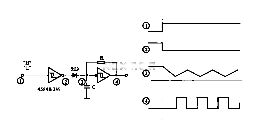
The circuit generates a controlled pulse signal. When a high pulse signal is applied to the input terminal O (start), the output pulse signal is activated. Conversely, when a low signal is received at the input terminal O (stop),...
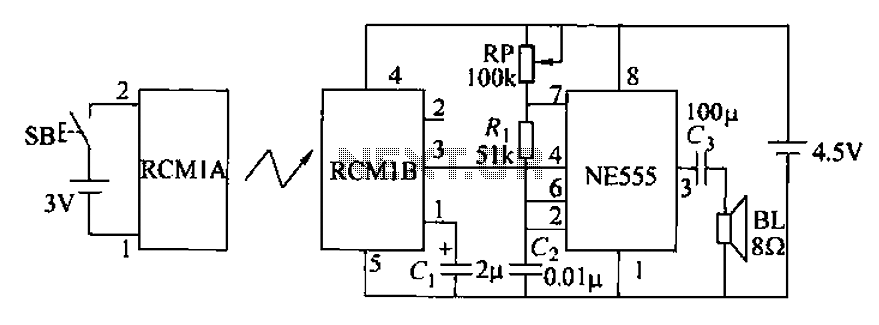
The circuit utilizes an RMIB multivibrator component that operates at a maximum distance. When the distance exceeds a specific threshold, the output pin of the receiver goes low, effectively stopping the oscillation. The NE555 multivibrator, which is part of...
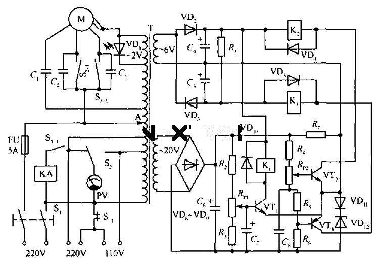
The circuit depicted in the figure includes an automatic voltage regulator (T) that maintains a constant output by utilizing a servo motor. The circuit features transistors VT1 and VT2 (3DK9), with a capacitance range of C (65 ~ 85)....