
Whistle Switch Circuit

The whistle switch circuit operates by utilizing the LM567 tone decoder, which is a versatile integrated circuit designed to detect specific frequencies. The circuit is initiated when the microphone (MIC1) captures sound waves, converting them into electrical signals. These signals are then amplified by the operational amplifier U2 to ensure sufficient signal strength for reliable tone detection.
The LM567 tone decoders U3 and U4 are configured to recognize a specific tone or frequency pattern. The design requires that the target tone be detected at least twice within a predetermined time interval, which enhances the circuit's resistance to false triggers caused by environmental noise or unintended sounds. This feature is crucial in applications where reliability is paramount.
Upon successful detection of the tone, the outputs of the tone decoders trigger the logic circuits within U5-a and U5-b. These logic circuits are responsible for processing the signals from the tone decoders and determining whether to activate the relay K1. The relay serves as a switch that can control various AC loads, allowing for versatile applications in automation or signaling systems.
The choice of relay depends on the specific AC load requirements, ensuring compatibility with different voltage and current ratings. This flexibility makes the whistle switch suitable for various applications, from activating alarms to controlling lights or other devices based on sound input. Overall, the circuit exemplifies an efficient and reliable design for sound-activated control systems. At the heart of the whistle swatch are a pair of tone detectors, each of which is built around an LM567 tone decoder, which are supported by a minimum of additional components. This whistle switch is designed to respond to only two or more occurrences of a specific tone, or sequence of tones, within a specified period to prevent false triggering.
Depending on the relay used, various ac loads can be controlled. Microphone MICl picks up the sound and U2 amplifies the signal and feeds it to tone decoders U3 and U4. These devices trigger U5-a and U5-b and the logic circuits that drive relay Kl.
Related Circuits

This document discusses a voltage stabilizer circuit utilizing the ICs 7815 and 7915, which requires an input voltage range of 17.5V to 50V. The output of this circuit consistently provides a regulated 15V output voltage. The stabilizer is further...
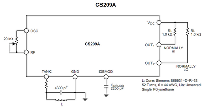
The operation principle of the proposed metal detector circuit is straightforward yet intriguing. The detection function is activated by sensing a decrease in the quality factor (Q) of the LC network associated with the circuit when a metal object...
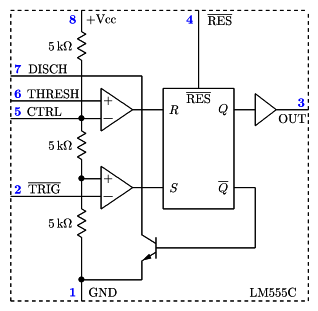
It is a typical Astable Multivibrator (AMV) setup. The capacitor charges through both resistors until it reaches 2/3 of Vcc, which is the level of the internal comparator. This triggers a flip-flop, activating the Discharge output (DIS). The capacitor...
The electronic motor speed controller circuit includes a wireless remote control transmitter circuit and a wireless remote control receiver circuit, as illustrated in the accompanying chart. The wireless remote control transmitter circuit comprises a micro-power wireless remote control transmitter...
The search coil, CI and C2, form a tuned circuit for the oscillator, which is tuned near the center of the broadcast band. Tune a portable radio to a station near the middle of the band, then adjust C2...
Developed as an interface between the General Instruments AY-3-8500-1 TV game chip and the antenna terminal of a TV set. Adjust capacitor C1 to the frequency of an unused channel to which the receiver is set for playing games....