
What is the purpose resistors and capacitor in this 555 circuit

The Astable Multivibrator (AMV) circuit utilizing the 555 timer functions as a square wave oscillator, generating a continuous output pulse without requiring any external triggering. The configuration consists of two resistors (R1 and R2) and a capacitor (C1), which together determine the frequency and duty cycle of the output waveform.
In this configuration, the capacitor C1 charges through resistors R1 and R2. The charging time is governed by the time constant, which is influenced by the values of R1, R2, and C1. When the voltage across C1 reaches 2/3 of the supply voltage (Vcc), the internal comparator within the 555 timer switches the state of the flip-flop, resulting in the activation of the Discharge output (DIS). This output is connected to ground, allowing the capacitor to discharge rapidly through the potentiometer (if included) and resistor R2.
The discharge continues until the voltage at the Trigger input (TRI) falls to 1/3 of Vcc. This threshold causes the flip-flop to reset, turning off the DIS output and allowing the capacitor to start charging again. The cycle of charging and discharging creates a square wave output at the output pin of the 555 timer, with a frequency determined by the values of R1, R2, and C1.
In terms of frequency (f) and duty cycle (D), the formulas for an AMV using a 555 timer are as follows:
- Frequency (f) = 1.44 / ((R1 + 2 * R2) * C1)
- Duty Cycle (D) = (R2 / (R1 + 2 * R2)) * 100%
This AMV configuration is widely used in various applications, including clock pulses, tone generation, and light flashers. The versatility of the 555 timer allows it to be utilized in both astable and monostable configurations, making it an essential component for electronic designers. The study of the 555 timer's block diagram and its operational principles is crucial for understanding its functionality and applications in electronic circuits.It`s a typical AMV (Astable MultiVibrator) setup. The capacitor gets charged through both resistors until 2/3 Vcc is reached (internal comparator level). This sets a flip-flop which activates the Discharge output (DIS). Through DIS and the potentiometer, the capacitor is discharged until the voltage on the Trigger input (TRI) is 1/3 Vcc, which resets the flip-flop
and switches off DIS, so that a new charging cycle starts. So the capacitor voltage swings between 1/3 Vcc and 2/3 Vcc, and each time one of the limits is reached the output toggles. It`s worth it to study the 555 block diagram and its typical applications, like this AMV or the MMV (Monostable MultiVibrator).
The 555 is one of the most versatile ICs around. 🔗 External reference
Related Circuits

This design outlines a simple wideband output amplifier suitable for use as a 50-ohm transmission line driver. The circuit is constructed using the CA3140 operational amplifier. When utilized alongside the function generator and sine wave shaper circuits, it delivers...
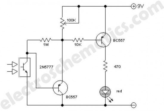
This enhanced infrared detector is designed for use with commercial infrared remote control handsets. This compact circuit is effective for quick go/no-go applications. The infrared detector circuit is engineered to respond to signals emitted by infrared remote control devices, commonly...
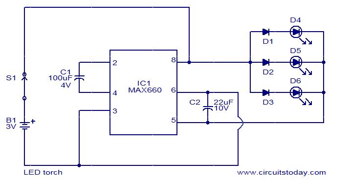
This circuit is a simple LED torch utilizing the MAX660 integrated circuit from MAXIM semiconductors. The MAX660 is a CMOS monolithic voltage converter IC capable of driving three bright white LEDs connected in parallel to output pin 8 of...
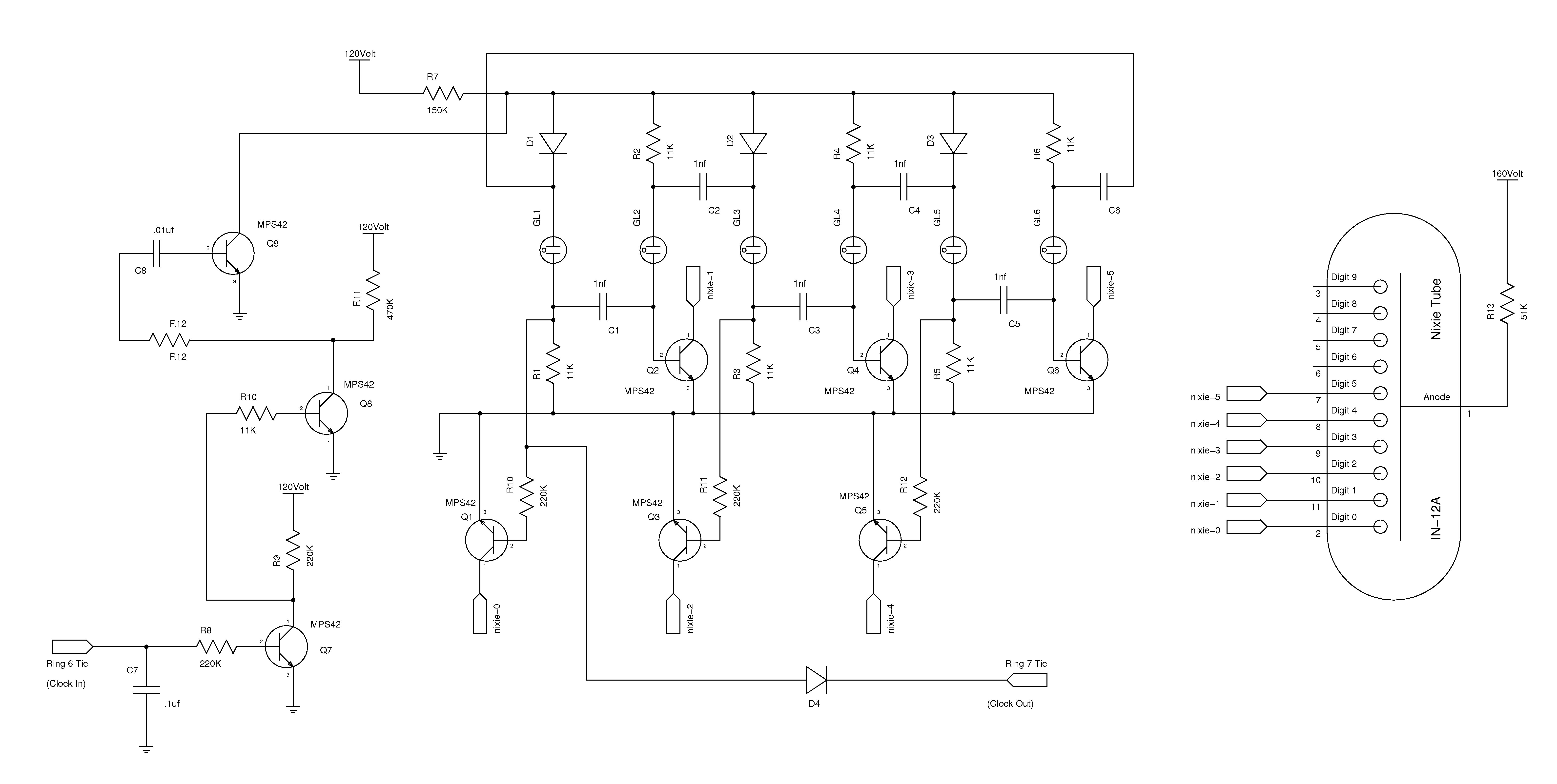
The nixie tube clock consists of a high-voltage power supply, seven ring counters, and an Atmel AVR processor. The power supply is shown in Schematic 1. It takes 12 volts AC and converts it to DC, which drives the...
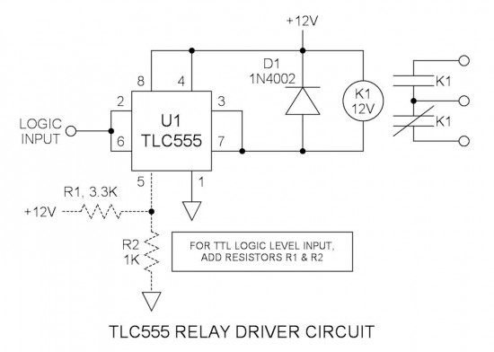
Many integrated circuits possess undocumented features or capabilities. One such example is the TLC555, which can sink a 100mA load down to 1.28V at its output (pin 3). The open-drain transistor reset (pin 7) can also sink 100mA to...
This system is designed to communicate or transmit a text message from one location to another using a wireless circuit. The text message is encrypted with a microcontroller, and the encrypted message is transmitted wirelessly. At the receiving end,...