
Whistle to beep circuit

The circuit utilizes a CMOS Hex inverter CD4049, which is a versatile component commonly used in various applications due to its low power consumption and high noise immunity. The microphone M1 acts as the input sensor, detecting the whistling sound. The audio amplifier configuration of U1a ensures that the weak signal from the microphone is sufficiently amplified to trigger subsequent stages of the circuit.
The band-pass filter designed with U1b is critical in isolating the desired frequency range. By focusing on the center frequency of around 2 kHz, the filter effectively allows whistling sounds to pass through while attenuating background noise and other irrelevant frequencies. This filtering capability is crucial for preventing false triggering, which could occur if the circuit responds to non-whistling sounds.
U1d, configured as a monostable multivibrator, introduces a time delay of 3 seconds. When activated by the amplified signal, it generates a single output pulse that lasts for the duration of the delay. This pulse then triggers the astable multivibrator formed by U1e and U1f, which produces a square wave output at approximately 4 Hz. This creates the intermittent beeping sound, as the astable multivibrator oscillates between its high and low states.
Transistor Q1 acts as a switch, controlled by the output from the monostable multivibrator. When Q1 is activated, it allows current to flow to the buzzer B1, generating the audible beep. The design of this circuit is straightforward yet effective, making it an excellent example of integrating basic electronic components to create a functional audio signaling device. This circuit can be further enhanced by incorporating additional features such as adjustable sensitivity or volume control to tailor its operation to specific applications.This simple circuit produces a beeping sound that lasts for around 3 seconds whenever you make a whistle. The CMOS Hex inverter CD4049 is the heart of this circuit. Out of the six inverters in CD4049, U1a is wired as an audio amplifier which amplifies the signal picked up by the microphone M1.
The U1b is wired as a band pass filter with center freq uency around 2KHz. The filter is necessary in order to pass the frequency corresponding to whistling sound and suppress all other frequencies. If the filter is not there, the circuit could easily get false triggered. U1d is wired as a 3S delay monostable multivibrator. The output U1d drives the astable multivibrator formed by U1e and U1f. The astable multivibrator is operating around 4Hz. The combined effect is a intermittent beeping sound that lasts for around 3S. Transistor Q1 is used to drive the buzzer B1. 🔗 External reference
Related Circuits
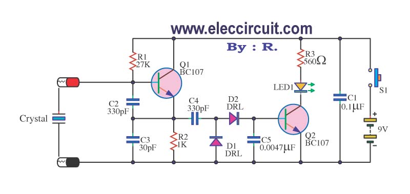
A multimeter cannot be used to test a crystal oscillator. Instead, a dedicated circuit is required, capable of checking crystals within the frequency range of 100 kHz to 900 MHz. This circuit is easy to construct and cost-effective. To construct...
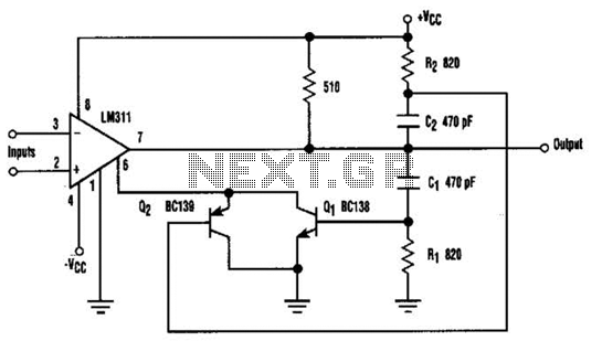
When the comparator's output transitions from low to high, the rising edge of the output pulse, differentiated by the Cl/Rl chain, activates Ql. This action blocks the comparator via its strobing input and maintains its output state for a...
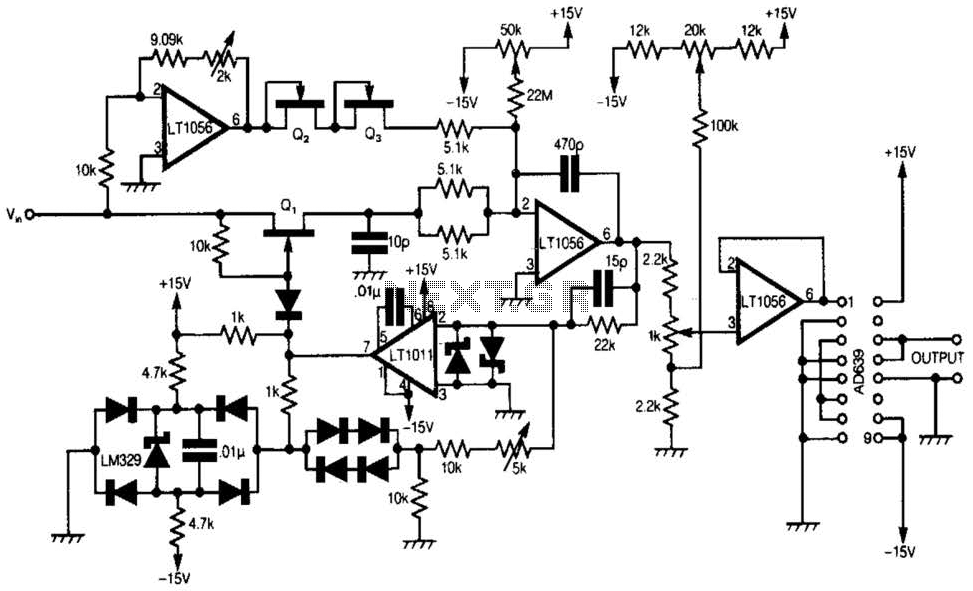
A 555 timer and a dual 556 timer are used to generate a basic video signal, as illustrated in the schematic. The first timer operates in astable mode, producing synchronization pulses with a period ranging from 4.7 to 8...
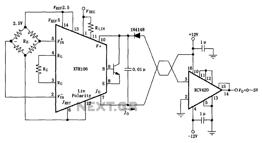
The IN4148 series diode is connected in the V+ line and configured in a loop to prevent damage from reverse voltage conditions. The diode exhibits a forward voltage drop of approximately 0.7V, which affects the supply voltage. The circuit...
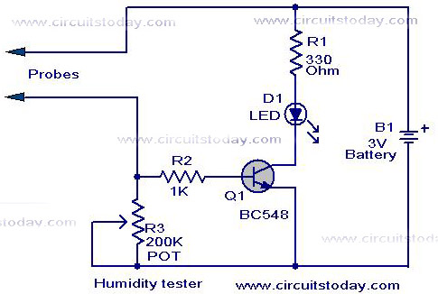
A simple humidity tester circuit using only an LED, a transistor, and a few resistors is explained with a clear circuit schematic. The humidity tester circuit is designed to provide a visual indication of humidity levels using basic electronic components....
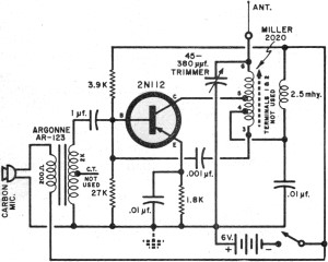
It had been a little over a decade since the invention of the transistor when this article appeared in the August 1959 edition of Popular Electronics. Transistors were still a mystery to many, including engineers, technicians, and hobbyists. Author...