
Who Press First Educational Game

The project is designed to engage users in a hands-on learning experience about digital electronics. It incorporates a NAND gate, which is a fundamental building block in digital logic design, to perform the necessary logical operations. The latch IC is employed to store the state of the button presses, ensuring that the project can accurately determine which participant was the quickest to respond.
The circuit typically includes four push-button switches, each representing one of the four participants. When a button is pressed, it sends a signal to the NAND gate, which processes the input and controls the output to the latch IC. The latch then retains the state of the first button pressed, effectively locking in the result until it is reset.
Additional components may include resistors to limit current, capacitors for debouncing the button presses, and possibly LEDs to provide visual feedback indicating which button was pressed first. A reset mechanism, such as a dedicated reset button or an automatic reset after a predetermined time, can be incorporated to allow for multiple rounds of play.
This educational game serves as an excellent platform for teaching concepts such as digital logic, timing, and state retention in electronic circuits, making it a valuable tool for both students and educators in the field of electronics.This electronics educational game uses a NAND IC, a Latch IC and a few peripheral components to construct a project that is able to tell who among the four person press the button first 🔗 External reference
Related Circuits

The FM Remote Control Receiver, available in the Infra-red circuits section of this website, features a connector that provides an analogue output. To create a simple intercom or public address (P.A.) system, the associated transmitter requires a microphone pre-amplifier...
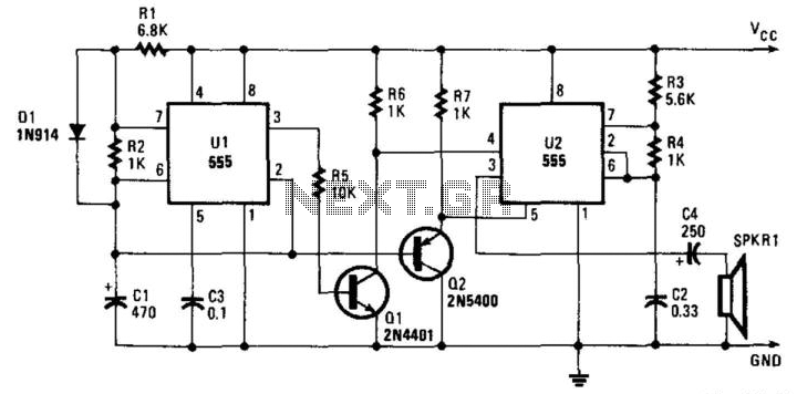
The integrated circuit U1 is configured as a low-frequency asymmetrical oscillator. Its output is inverted by Q1 and sent to the reset terminal of U2 at pin 5. Integrated circuit U2 operates as an audio oscillator and is activated...
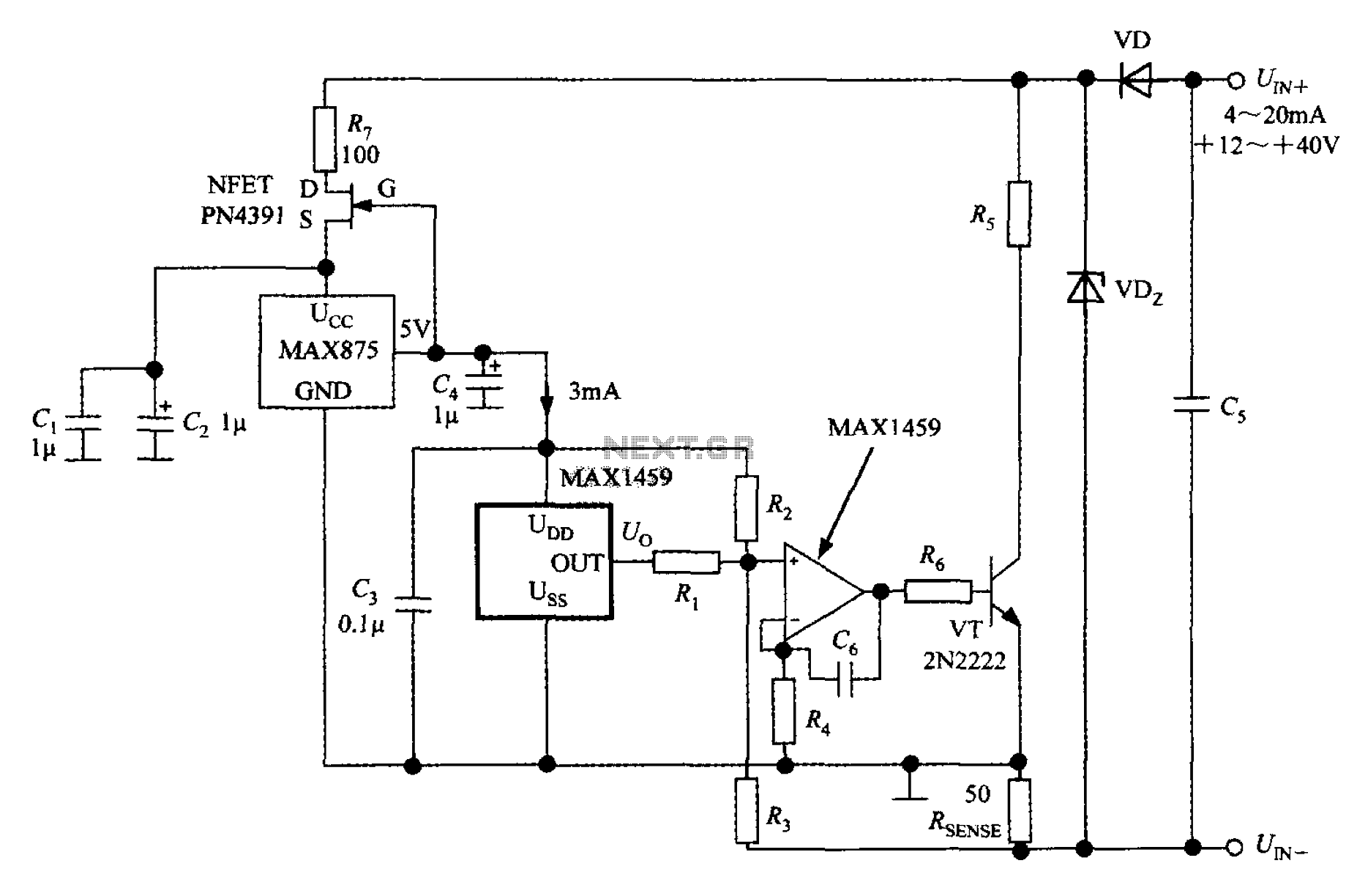
A 4 to 20 mA current transmitter circuit is implemented using the MAX1459, as illustrated in the accompanying figure. The output voltage from the programmable gain amplifier (PGA) is supplied to a spare amplifier chip, and subsequently, an external...
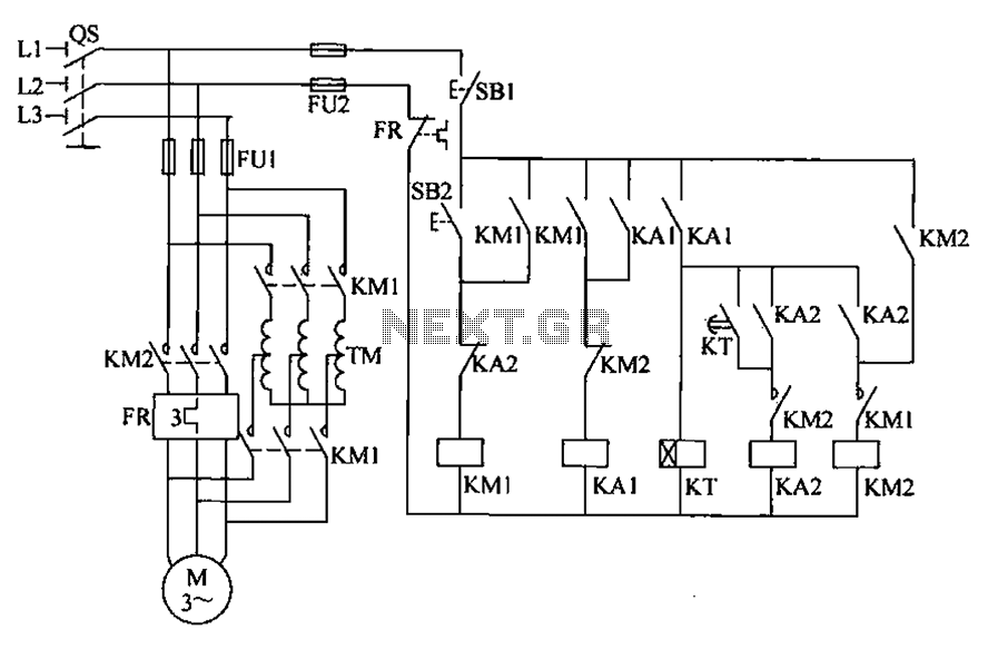
To initiate the system, turn off the power switch, then press the start button SB2. The KM1 contactor is energized, engaging self-locking, and closing the main contacts. The autotransformer TM is connected between the power source and the motor,...
This jam circuit can be used in quiz contests wherein any participant who presses his button (switch) before the other contestants, gets the first chance to answer a question. The circuit given here permits up to eight contestants with...
RCA developed some of the first commercially available CCD (Charge-Coupled Device) chips. A CCD is a silicon-based solid-state imaging device that replaces the older vidicon tubes. CCDs consist of a two-dimensional array of photodetectors linked to an array of...