
Wideband uhf amplifier with high-performance fets

The amplifier circuit operates at a center frequency of 225 MHz, which is optimal for various communication applications. The design incorporates a 1 dB bandwidth of 50 MHz, allowing for effective signal amplification while maintaining signal integrity across the specified frequency range. A low input VSWR is achieved in a 75-ohm system, which is critical for minimizing signal reflections and ensuring maximum power transfer from the source to the load.
The use of three stages of U310 FETs (Field Effect Transistors) is a key aspect of the design. These FETs are known for their high gain characteristics and low noise figure, making them suitable for RF amplification. The straightforward design approach ensures that the amplifier is both efficient and reliable, capable of delivering a consistent gain of 24 dB across the operating frequency range.
In terms of circuit topology, the amplifier can be implemented using a common source configuration for each FET stage, which provides the necessary voltage gain while maintaining a good input and output impedance match. Biasing networks are essential to ensure that the FETs operate in the desired region of their transfer characteristics, thus optimizing performance.
Additional components such as matching networks may be included at the input and output to further enhance the amplifier's performance, ensuring that the impedance is well-matched to the 75-ohm system. This matching is crucial for achieving low VSWR and maximizing the efficiency of the amplifier.
Overall, the design of this amplifier circuit is tailored to meet specific performance criteria, making it suitable for applications that require reliable signal amplification at RF frequencies.The amplifier circuit is designed for 225 MHz center frequency, 1 dB bandwidth of 50 MHz, low input VSWR in a 75-ohm system, and 24 dB gain Three stages of U310 FETs are used in a straight forward design.
Related Circuits
The objective of this design is to create a Combo amplifier that was popular during the 1960s and 1970s. It is particularly effective as a guitar amplifier but can also perform well with various electronic musical instruments or microphones....
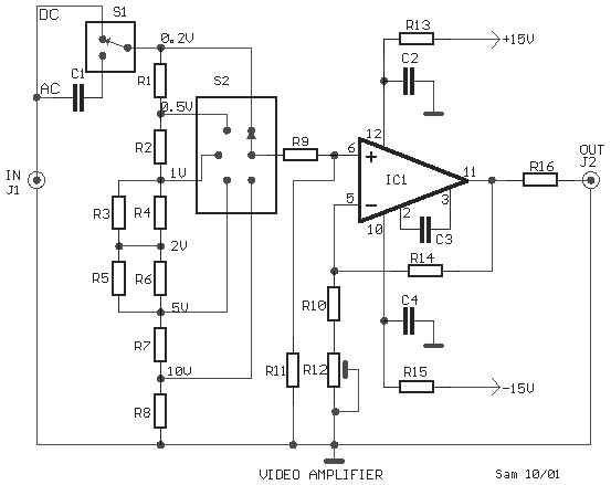
This is a schematic diagram of a video amplifier circuit, built using the very high-speed operational amplifier IC LH0032. Parts List: R1 = 15KΩ, R2, R3, R4 = 10KΩ, R5, R6, R7, R8, R9 = 1KΩ, R10 = 820Ω,...
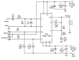
This audio amplifier circuit utilizes the TDA7294, a power integrated circuit designed for high-quality audio applications. The TDA7294 operates as a class AB amplifier, characterized by low noise and distortion levels, a wide bandwidth, and robust output current capability....
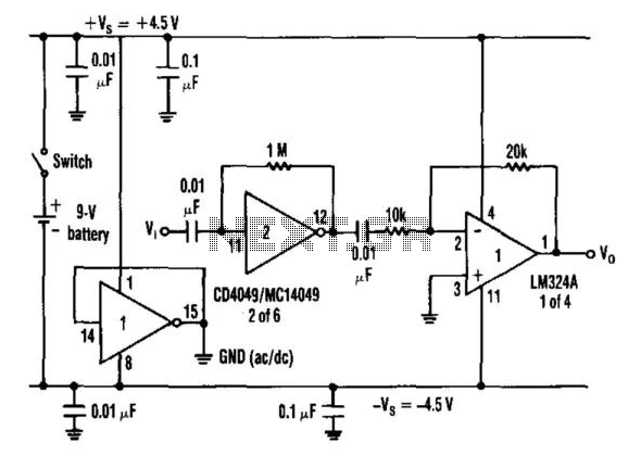
When an inverter is biased with a resistor from its input to output in the range of 100 kΩ to 10 kΩ and is capacitor coupled, it exhibits amplifier characteristics. Furthermore, when a split power-supply bus is needed and...

This circuit is a FET Cascode Video Amplifier. The cascode amplifier FET used for video applications has a very low input impedance and nearly zero feedback reduction. The 2N3823 transistor was selected due to its low capacitance and high...
This article lists various types of audio amplifier circuits using MOSFETs. All circuits have been tested in a laboratory environment and have shown satisfactory performance. The amplifier utilizes one transistor, two MOSFETs, and a few resistors and capacitors in...