
wien bridge oscillator distorted output

To mitigate the "hump," increasing the output voltage can help make the distortion less significant relative to the total amplitude. This involves increasing the gain and ensuring that the power supply voltage is adequate. Additionally, softening the diode curves by placing a resistance in series with them can be beneficial. By using a larger resistance value in conjunction with the diodes, automatic gain adjustment can still be achieved. For instance, starting with a 20k resistor in series with the diodes and a 50k resistor in parallel, while adjusting the impedance of the feedback network, can provide a cleaner output.
The LM358 has limitations, including a low slew rate, which restricts its performance above 2kHz, while audio frequencies can reach up to 20kHz. The distortion in the oscillator waveform is a result of the delay caused by the clipping diodes. Additionally, the low power output transistors may not be adequately biased, leading to crossover distortion, which is undesirable in sine wave oscillators and audio applications.
The LM358 can function as an op-amp but has restrictions on frequency and gain bandwidth that define its suitability for specific applications. Proper biasing is crucial for minimizing distortion. The LM358 is often criticized due to misconceptions stemming from errors in the datasheet, which may have been authored by someone not directly involved in the product's design. This can lead to widespread misinformation regarding its performance.
To clarify, while the LM358 has its limitations, it is not inherently a poor product; rather, misconceptions and erroneous information have contributed to its negative reputation. Proper understanding and usage of the device can yield satisfactory results.
The LM358 is a dual operational amplifier with a low power consumption characteristic, making it suitable for battery-operated devices. However, its low slew rate (typically around 0.3 V/µs) limits its application in high-frequency circuits, particularly in audio applications where frequency response is critical. The distortion introduced by the diodes in the feedback loop can be addressed by implementing a more suitable feedback mechanism that minimizes abrupt changes in gain.
In practical applications, a Wien bridge oscillator using the LM358 should consider incorporating nonlinear elements that can provide smoother gain adjustments, such as using a thermistor or a lamp for feedback, rather than relying solely on diodes, which can introduce unwanted artifacts in the output signal. Additionally, careful layout considerations should be taken to minimize parasitic capacitance and inductance, which can further deteriorate high-frequency response.
In conclusion, the LM358 can be effectively utilized in various applications if the design considerations are adequately addressed, particularly concerning biasing, feedback mechanisms, and component selection. Properly designed circuits can achieve clean sine wave outputs and avoid common pitfalls associated with this operational amplifier.try another op amp. I could be changes in the input bias current that is causing a strange voltage drop across the 10k resistors. The LM358 is not really a high quality op amp it`s the diodes in the feedback loop. that`s a poor choice of limiter for a sine wave oscillator. usually wien bridge oscillators use a slow nonlinear element for maintainin g a constant signal, such as an incandescent lamp or a fet driven by a rectified and filtered portion of the output signal. I have to agree that the main reason for the `hump` is because of the diodes. The diodes have a relatively sharp IV curve so although they do limit the gain, they do so very abruptly and this shows up as distortion on the output.
This of course assumes that the frequency of operation is within the limit that the op amp can easily handle. First is to increase the output voltage so the hump isnt as significant relative to the total amplitude.
This means increasing the gain and making sure the power supply voltage is high enough. Second, you can soften the two diode curves by placing a resistance in series with them. You then work the diodes plus series resistance against a bigger resistance value (bigger than 10k) so you still get automatic gain adjustment. Say you start with 20k in series with the diodes, then maybe 50k in parallel and adjust the impedance of the other two resistances in the negative feedback network to provide approximately the same gain (but maybe a bit higher as above).
Once the diode curves are softened the gain change wont be as abrupt and should provide for a cleaner output. So really all you would be doing is placing a resistance in series with the two diodes, then adjusting the impedance of the other negative feedback elements (going higher) so they can still work effectively with the `new` diodes.
It is low power so it has a poor high frequency response. Its slew rate is so low that it has trouble above only 2kHz. Audio goes up to 20kHz. The "hump" in the oscillator waveform is caused by the delay of the distortion caused by the clipping diodes. It is low power so its output transistors are not biased enough so it has crossover distortion. You do not want crossover distortion in a sinewave oscillator nor in audio. Where did you get that scope picture from That crossover distortion looks to be too great even for the LM358.
Can you post a schematic of the circuit that was used to create that scope shot LM358`s do work up to a certain point for frequencies lower than some limit set by the slew rate and gain bandwidth product. They should be able to produce a clean enough sine wave for some applications. They do however require proper biasing to get good response. The LM358 functions as an op amp but it does have some restrictions on frequency and gain bandwidth which set the upper limit for use in a given application.
Also, to get good distortion the op amp has to be properly biased. The poor LM358 often gets a bad rap for a number of reasons, probably the main reason for this is that there are several significant errors on the data sheet. When i read the LM358 data sheet i get the feeling that one of the oldest problems in manufacturing products for public use comes up: the person who wrote the datasheet/manual was not the same person that designed the product.
The errors can be subtle, but the ramifications are anything but subtle and lead to gross misuse of the product. This leads to the informational domino effect, where one person tells another person tells another person, and soon everbody thinks the product doesnt work right.
It`s not the individual people`s fault either, it`s the manufacturers fault for allowing the bad information to hit the market. So it`s not really a bad product, it`s bad information, and since it comes directly from the manufacturer there is no reason not to believe the false information.
Im going to attempt to clear up this problem once and for all with the LM358. The data sheet tries to explain how to use this thing effectively, but fails because whoever wrote it either didnt understand the device themselves or simply made a subtle error because of a small oversight. It is low power so it has a poor high frequency response. Its slew rate is so low that it has trouble above only 2kHz. Audio goes up to 20kHz. The "hump" in the oscillator waveform is caused by the delay of the distortion caused by the clipping diodes.
It is low power so its output transistors are not biased enough so it has crossover distortion. You do not want crossover distortion in a sinewave oscillator nor in audio. Well I have to disagree. I have used the 358 in many circuits without any of the issues highlighted here. I suspect many of the problems are layout/component choices or simply forgetting what to do with the other half of the op amp since they share the same substrate. 🔗 External reference
Related Circuits
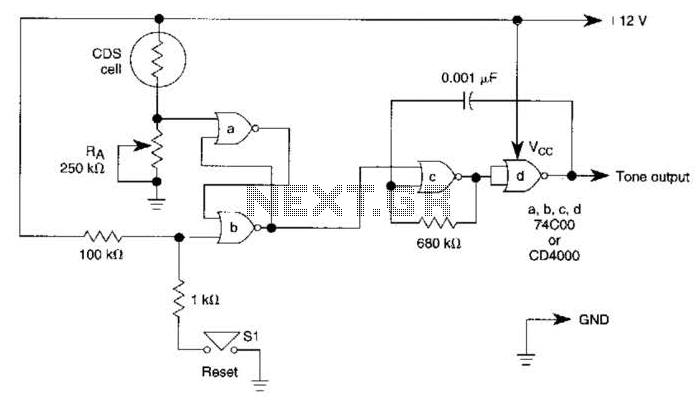
A decrease in the resistance of the CDS cell when light strikes it activates latch A and B, enabling tone oscillator C and D, which produces an output of about 1000 Hz. RA sets the trip level. SI resets...
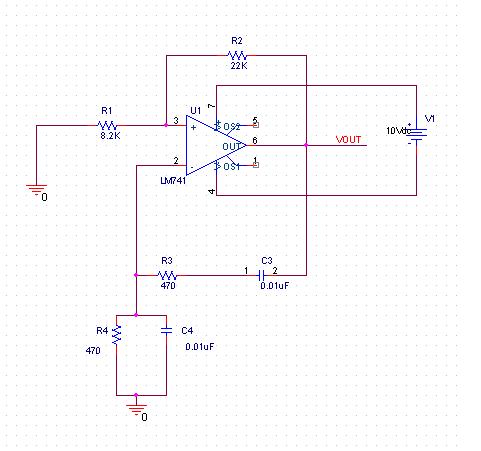
A practical project is being conducted using the LM741 operational amplifier configured as a Wien bridge oscillator. The component values are specified as follows: C1 = C2 = 0.01 µF, R1 = R2 = 3 kΩ, Rf = 2...
A NE555 integrated circuit (IC) is utilized for the design of a variable low-frequency oscillator, and a schematic is provided. The NE555 timer IC is a versatile and widely used device in various electronic applications, particularly in generating precise timing...
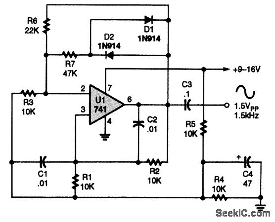
A 741 operational amplifier is configured within a Wien-bridge audio sine-wave oscillator circuit. The components C1, C2, R1, and R2 are responsible for determining the operating frequency of the circuit. By utilizing NPO capacitors and metal-film resistors, the oscillator...
This application note analyzes the details of a Wien-bridge oscillator, shows how a JFET maintains oscillation, and demonstrates adding a digital potentiometer (digipot), rather than a variable resistor, to improve stability and flexibility. The Wien-bridge oscillator is a type of...

This design outlines a simple wideband output amplifier suitable for use as a 50-ohm transmission line driver. The circuit is constructed using the CA3140 operational amplifier. When utilized alongside the function generator and sine wave shaper circuits, it delivers...