Wilf Rigter`s SIMD1 V1
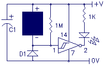
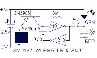
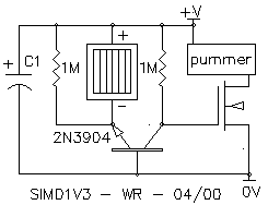
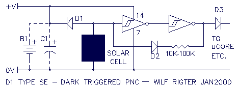
Normally the active high output from the inverter is used to enable the remainder of the CMOS gates which then perform some useful function. When the SIMD1 triggers at night, it snaps on and the output signal can be used to control the 5 remaining 74HC14 inverters connected in parallel with the outputs used as a "power" switch. Or the signal can be used as the tristate control of a 74HC240 or 74HC245 or be used as a PNC input for an Nv net etc. to apply the stored energy to the load.
The described circuit utilizes a CMOS inverter, specifically the 74HC14, which is a hex inverting Schmitt trigger. The active high output from this inverter acts as a control signal to enable additional CMOS gates, allowing them to perform various functions based on the input conditions. The circuit is particularly designed to operate in a low-power environment, where the SIMD1 component triggers at night, indicating a transition to a different operational mode.
When the SIMD1 activates, it sends a high signal output that can drive multiple 74HC14 inverters arranged in parallel. This configuration allows for increased current handling capability, effectively functioning as a power switch. Each of the five inverters can provide a high output to control larger loads or other circuitry, ensuring that the system can manage higher currents without compromising performance.
Additionally, the output signal can be utilized as a tristate control for bus drivers such as the 74HC240 or 74HC245. These devices are designed to manage data transmission on a bus system, where they can either drive the bus high, low, or enter a high-impedance state, allowing for multiple devices to share the same communication lines without interference.
Furthermore, the output can serve as a PNC (Power Network Control) input for an Nv net, facilitating the application of stored energy to the load. This implies an integration with energy storage systems, where the circuit can effectively manage energy distribution based on the control signals provided by the SIMD1 inverter.
Overall, this circuit design emphasizes versatility and efficiency in power management and control functions, leveraging the capabilities of CMOS technology to adapt to varying operational requirements. The use of parallel inverters and bus drivers enhances the circuit's robustness, making it suitable for applications that demand reliable performance in energy-sensitive environments.Normally the active high output from the inverter is used to enable the remainder of the CMOS gates which then perform some useful function. When the SIMD1 triggers at night, it snaps on and the output signal can be used to control the 5 remaining 74HC14 inverters connected in parallel with the outputs used as a "power" switch.
Or the signal can be used as the tristate control of a 74HC240 or 74HC245 or be used as a PNC input for an Nv net etc. to apply the stored energy to the load. 🔗 External reference
