Wilf Rigter`s SIMD1 V3
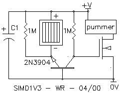
The SIMD1 V3 is very similar to the NPN flavor of SIMD1 V2, but with the addition of a FET on the output line. This makes life easier for its attached load (since there's no need here for something that can use an "enable line"), by providing power that's just "there" in the dark. Here the FET is used to sink load current from a pummer, motor, or whatever.
The SIMD1 V3 circuit integrates a Field Effect Transistor (FET) in its output stage, enhancing its functionality compared to the SIMD1 V2. The FET operates as a low-resistance switch, allowing for efficient current sinking from various loads such as pumps or motors. This configuration eliminates the necessity for an enable line, simplifying the design and control of connected devices.
In operation, when the input signal is applied, the FET becomes conductive, allowing current to flow from the load to ground. The FET's gate is controlled by the input signal, which determines whether the load is powered or not. This arrangement ensures that power is readily available to the load without requiring additional control signals, which can be particularly advantageous in applications where simplicity and reliability are paramount.
The circuit design must ensure that the FET is appropriately rated for the maximum load current and voltage to prevent thermal overload and ensure stable operation. Proper heat dissipation mechanisms, such as heat sinks or thermal pads, may also be necessary depending on the power levels involved. Additionally, the circuit should include protective components, such as diodes for back EMF protection when driving inductive loads like motors, to safeguard the FET and other sensitive components.
Overall, the SIMD1 V3 offers an efficient and straightforward solution for driving loads in electronic applications, making it a valuable component in various systems requiring reliable power delivery without complex control mechanisms.The SIMD1 V3 is very similar to the NPN flavor of SIMD1 V2, but with the addition of a FET on the output line. This makes life easier for its attached load (since there`s no need here for something that can use an "enable line"), by providing power that`s just "there" in the dark.
Here the FET is used to sink load current from a pummer, motor, or whatever. 🔗 External reference
