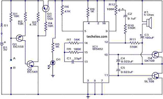
Wire Break Sensor Alarm Circuit Schematic
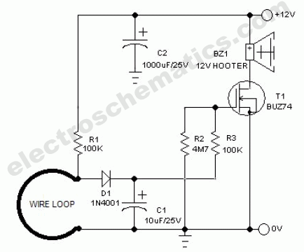
The circuit of a loop sensor-based simple security alarm is described here. The sensor loop consists of a short length of thin enamelled copper wire.
The loop sensor security alarm operates on the principle of detecting interruptions in the circuit formed by the loop of copper wire. When the loop is intact, the circuit remains closed, allowing current to flow through the system. This current can be monitored by a microcontroller or a comparator circuit, which is configured to detect changes in voltage levels across the loop.
In the event that an intruder cuts or opens the loop, the circuit becomes open, and the current flow is interrupted. This change is detected by the monitoring system, which triggers an alarm signal. The alarm can be a simple buzzer or a more sophisticated notification system, such as a connected smart home device that sends alerts to a mobile application.
The basic components of the circuit include the loop of enamelled copper wire, a power supply (typically a 9V battery), a resistor to limit the current, a transistor or a relay to activate the alarm, and an audible alarm device. The loop wire should be installed in a strategic location, such as door frames or windows, where it is less likely to be disturbed during normal activity.
The design of the loop sensor security alarm can be further enhanced by including features such as adjustable sensitivity, a delay timer to prevent false alarms, and integration with other security systems. Additionally, the circuit can be protected against environmental factors by using weather-resistant materials for outdoor installations.
Overall, the loop sensor-based security alarm provides a simple yet effective solution for home security, utilizing basic electronic components to create a reliable and efficient monitoring system.Circuit of a loop sensor based simple security alarm is described here. The sensor loop is nothing but a short length of thin enamelled copper wire, which.. 🔗 External reference
