
TLE5206-2 H-Bridge Circuit Application and Datasheet

The TLE5206-2 is a versatile integrated circuit optimized for controlling DC motors in various applications. It operates using a dual H-bridge configuration, allowing for bi-directional control of the motor. The DMOS output stages provide high efficiency and the capability to handle up to 5A of continuous current, making it suitable for driving larger motors.
The input circuit of the TLE5206-2 is designed to accept control signals that dictate the direction and speed of the motor. These control signals can be generated by a microcontroller or other logic devices. The H-bridge configuration allows for both forward and reverse operation of the motor, with PWM (Pulse Width Modulation) signals enabling speed control by varying the duty cycle.
The output stages are equipped with protection features that ensure the reliable operation of the motor and the circuit. The undervoltage lockout feature prevents the device from operating under insufficient supply voltage, which could lead to erratic behavior. The error flag can be set under several fault conditions, providing feedback to the controlling device about the operational status of the motor.
The protective functions include output shorted to ground detection, which safeguards the circuit against potential damage from a short circuit condition. Similarly, output shorted to VS detection prevents damage from excessive current draw. Overload detection monitors the current flowing through the motor, allowing the circuit to take corrective action if the current exceeds safe levels. Lastly, over-temperature protection ensures that the device operates within safe thermal limits, shutting down the output if temperatures rise too high.
Overall, the TLE5206-2 is a robust solution for DC motor control, combining advanced features with ease of integration into various electronic systems. Its comprehensive protection mechanisms enhance reliability and longevity in demanding applications.The schematic below showsTLE5206-2 5A H-Bridge for DC Motors Circuit Application. It such a device which has an integrated power H-bridge with DMOS output stages for driving DC-Motors, according to the datasheet. TLE5206-2 Circuit Application describes Input Circuit, Output Stages, Undervoltage Lockout, setting of the Error Flag in Protective Func
tion (Output Shorted to Ground Detection, Output Shorted to VS Detection, Overload Detection, Over Temperature Protection). 🔗 External reference
Related Circuits
This is a very simple FM receiver built using only one transistor. It does not utilize any chips or other active components. The output is connected to earphones; an amplifier circuit is required if the radio is to be...
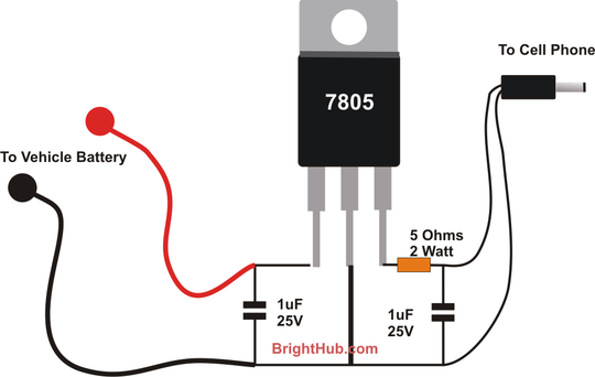
With the advent of modern integrated circuits (ICs), sophisticated circuits today are no longer required to be complex and lengthy. The chips themselves contain most of the intricate circuitry built-in and can independently perform the desired functions. For instance,...
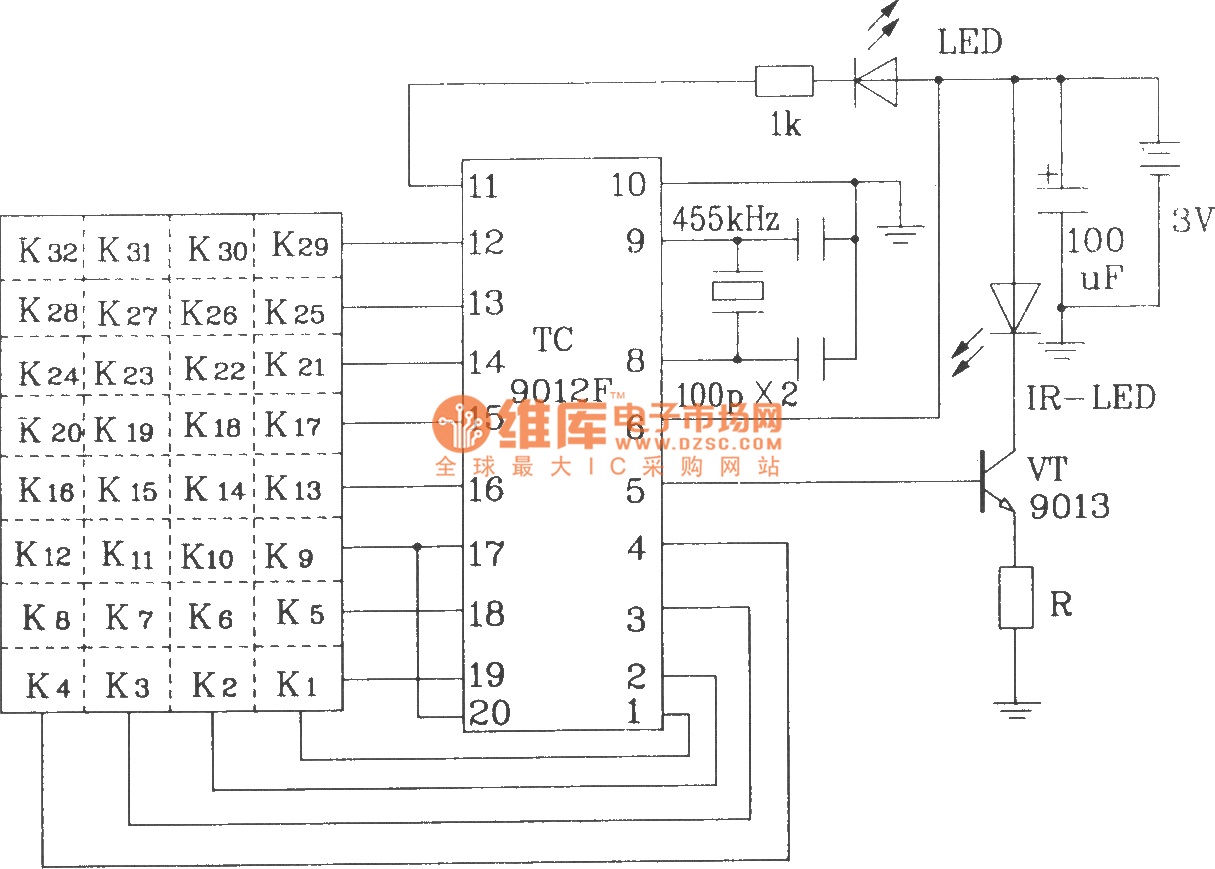
The TC9012 is a specialized off-screen remote control code transmitter. It incorporates an oscillator, divider timing generator, system code latch, data storage, key scan input, key scan output, and carrier control and output units. The internal 8-bit system code...
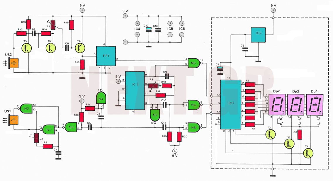
The circuit utilizes ultrasonic oscillations to measure the distance between two points based on the speed of sound in air. By measuring the time it takes for the ultrasonic wave to travel between these points, the distance can be...
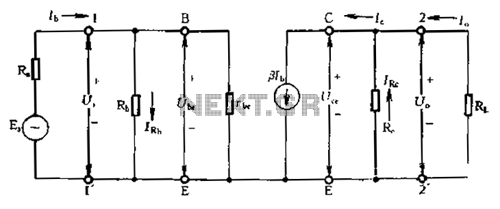
Calculate magnification, input resistance, and output resistance circuit. This circuit is designed to calculate the magnification, input resistance, and output resistance of a given electronic system. The magnification refers to the ratio of the output signal to the input signal,...
As shown in the figure, the 555 timer, resistors R1, RP1, and capacitor C1 form a controlled audio oscillator. The frequency of the oscillator is given by the formula f = 1.44 / ((R1 + 2 * RP1) *...