Wire loop alarm
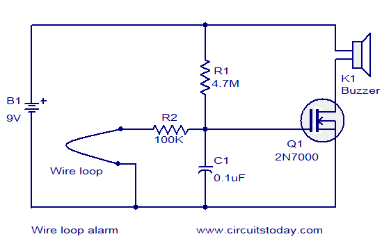
The circuit diagram illustrates a simple wire loop alarm utilizing an N-channel enhancement FET 2N700, a buzzer, and several passive components. Under normal conditions, the gate of the 2N700 (Q1) is connected to the ground through a 100K resistor (R2) and the wire loop. When the wire loop is interrupted, Q1 becomes biased to the ON state, activating the buzzer. The circuit exhibits minimal standby current consumption, allowing the battery to last for an extended duration.
The wire loop alarm circuit operates on a straightforward principle of detecting interruptions in a closed loop. The N-channel enhancement FET 2N700 serves as the primary switching element. In its default state, the gate of Q1 remains at ground potential due to the connection through resistor R2, which effectively keeps the FET in the OFF state. This configuration prevents current from flowing through the buzzer, ensuring that it remains silent.
When the wire loop is intact, the circuit maintains a low power state, characterized by minimal current draw, which is advantageous for battery-operated applications. The high resistance value of 100K for R2 ensures that the circuit does not drain the battery unnecessarily during standby.
Upon breaking the wire loop, the gate voltage of Q1 changes, allowing the FET to enter the ON state. This transition occurs because the interruption causes a change in the potential at the gate, leading to the conduction of current from the drain to the source of the FET. Consequently, the buzzer is activated, producing an audible alert to indicate that the loop has been compromised.
The design of this circuit can be further enhanced by incorporating additional features such as an LED indicator to visually signal the alarm state, or a more sophisticated power management system to optimize battery usage. Overall, this wire loop alarm circuit is an effective and efficient solution for basic security applications, providing reliable operation with minimal power consumption.Here is the circuit diagram of a very simple wire loop alarm based on a N-channel enhancement FET 2N700, a buzzer and few passive components. In normal condition the gate of 2N700 (Q1) is connected to the ground through a 100K resistor (R2) and the wire loop.
When the wire loop is broken, Q1 will be biased to ON state and the buzzer is activated. T he circuit consumes very less standyby current and so the battery will last for a very long period of time. 🔗 External reference
