
Simple One-Wire Touch Detector circuit

The described circuit operates based on the principle of capacitive touch sensing. When a user touches the metal plate, it alters the capacitance at that point, which influences the voltage across the voltage divider formed by resistors R1 and R2. This change in voltage is detected by the input of the Schmitt trigger gate, which has a hysteresis characteristic that provides a clean transition between the high and low states.
The output of the Schmitt trigger can be used to drive various loads, such as relays or microcontrollers, allowing for a wide range of applications. The inclusion of a capacitor in the circuit serves to filter out any high-frequency noise, ensuring stable operation. LED1 provides a visual indication of the circuit's activation state, while resistor R3 limits the current flowing through the LED to prevent damage.
Overall, this circuit design is compact and versatile, making it suitable for various electronic projects that require touch activation or sensing capabilities. Proper selection of resistor values and the capacitor will ensure optimal performance and responsiveness of the touch-sensitive feature.This simple circuit can be used to activate whatever you like, for example, by connecting it to microcontroller, relays, secret alarms, robot applications or just turn on LED1 which lights up as long as you touch the metal plate. The circuit consists of voltage divider R1 and R2, one Schmitt trigger/inverter gate from a 40106 IC, a small capacitor to keep strong RF at bay and LED1 with current limiting resistor R3.
The metal plate is connected via a wire to R1. R1 and R2 together form a voltage divider.. 🔗 External reference
Related Circuits
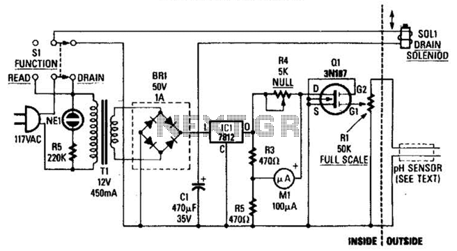
The drain-to-source resistance of Q1 varies depending on the acidity of the sample presented to Q1's gate circuit. This variable resistance influences the current flowing through the bridge, which is proportional to pH. The circuit involves a field-effect transistor (FET),...
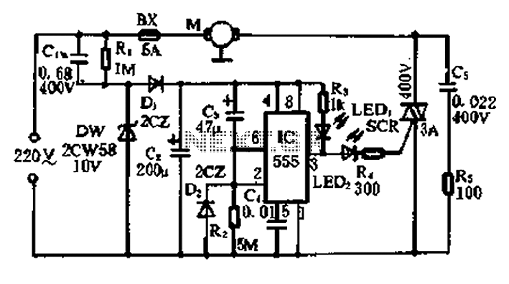
A 5-minute circuit can continue to operate during a power outage, providing protection for the refrigerator. The refrigerator power protection circuit, designated as 1136, includes a power transformer that converts 220V voltage through a rectifier bridge (VD1). This setup...

The circuit employs a field-effect transistor (FET) at the input of a Schmitt trigger, allowing the use of a low-value capacitor. The trigger, controlled by Q1 and O2, exhibits a hysteresis of approximately 3V, regulated by a 3V zener...
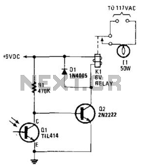
A phototransistor detects daylight. At dusk, it stops conducting, and Rl biases Q2, activating Kl, which turns on the light. At dawn, Ql begins to conduct, cutting off Q2. Kl deactivates, and the light turns off. The circuit utilizes a...

This is a UHF band TV antenna preamplifier circuit with a gain of 15 dB, built using a BF180 UHF transistor. The circuit is straightforward in design. The operational principle consists of two stages. The first stage features a...
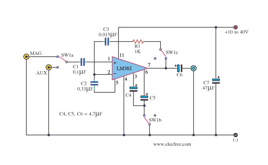
This is a simple preamplifier circuit. It can accept a general AUX sound signal as well as a signal from a microphone. The purpose of the circuit is to amplify the sound signal at the initial stage using an...