
wire tracer circuit

The circuit described operates within a frequency range that allows for effective signal transmission and reception, which is critical for applications such as wire tracing and fault detection. The use of a 556 timer, which contains two timing circuits, enhances the functionality of the transmitter by enabling frequency modulation. The first timer (IC1b) generates a square wave signal, while the second timer (IC1a) modulates this signal, providing a variable output frequency that can be adjusted for optimal performance based on the specific requirements of the testing environment.
The antenna, a simple wire connected to resistor R6, plays a crucial role in radiating the generated signal. Its length is carefully chosen to optimize the transmission characteristics at the frequencies being used. The ground connection ensures that the circuit operates effectively by providing a stable reference point, which is essential for accurate signal transmission and reception.
This device is particularly beneficial for technicians and electricians who need to trace wiring paths or locate breaks without the need for invasive methods. The straightforward design allows for easy assembly and use, making it accessible for both professionals and hobbyists. By employing this circuit, users can efficiently identify and troubleshoot wiring issues, improving overall maintenance and repair processes in electrical systems.The output frequency alternates between about 2100 Hz and 2200 Hz. This is a very distinctive test signal that is easily distinguished from any other signals that may be present. Resistor R6 is connected to a piece of wire, about ten centimeters long, that functions as the antenna. The ground connection (junction C2-C3) is connected to ground. When the antenna is connected directly to a cable, it is possible to determine at the other end of the cable, with the aid of the receiver, which conductor is which (don`t do this with live conductors!).
The schematic for the matching receiver may be found elsewhere in this website. The circuit depicted here forms one half of a device that will prove extremely handy when tracing the path of electrical wiring in a building or to locate a break in a wire. The system is based on similar equipment that is used by technicians in telephone exchanges. The operation is straightforward. You require a generator that delivers an easily recognizable signal which, using a short antenna, is inductively coupled to a simple, but high gain, receiver.
To create a useful transmitter it would suffice to build a simple generator based on a 555. But as the adjacent diagram shows, a 556 was selected instead. The second timer (IC1a) is used to modulate the tone produced by IC1b. 🔗 External reference
Related Circuits
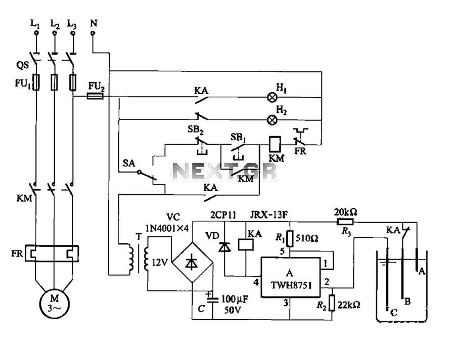
The power switch integrated circuit A features a straightforward design with high sensitivity, ensuring reliable operation. It is part of an automatic liquid level control circuit. When the water level at electrode B drops below 2 feet (0V), circuit...
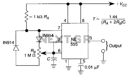
A 1.2-kHz oscillator utilizing a potentiometer and steering diodes allows for a duty cycle adjustment ranging from 1% to 99%. The frequency can be altered by varying the capacitor CI. It is important to note that the diodes may...
Wireless headphone transmitter and receiver systems are now widely available in the market, offering a variety of pricing options along with reliable technical specifications for various applications. These include wireless headphones for televisions, computers, and earbuds. A wireless headphone...

This car audio amplifier circuit is based on the LA47536 audio amplifier integrated circuit designed by Sanyo. This audio amplifier circuit is specifically designed for car audio power amplifiers. The LA47536 car audio amplifier IC features four output channels...
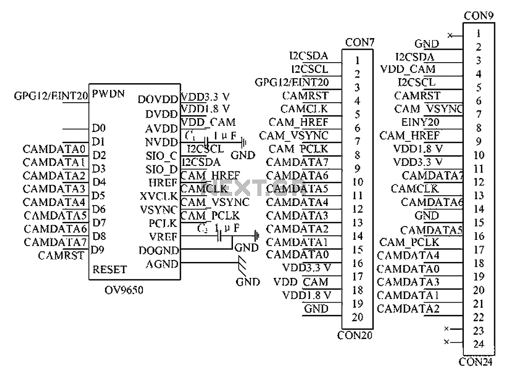
The circuit principle involves the OV9650 processor, which interfaces through three components: the SCCB interface, the data output interface, and the control interface. The SCCB interface is responsible for transferring initialization parameters from the processor's internal registers. It utilizes...
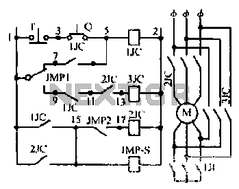
Motor windings are set to connect in a Y configuration while the load is active. The system includes an electric suction mechanism, and the motor is designed to operate under specific conditions. It is rated for 600 revolutions per...