
Wireless Headphones Transmitter Circuit

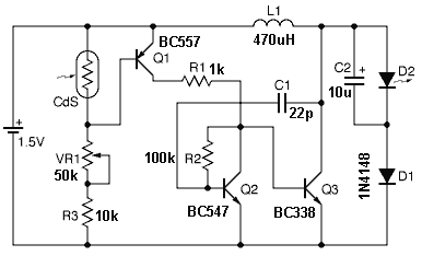
The wireless headphones transmitter operates within a frequency range of 1750 kHz to 3500 kHz, making it suitable for various audio transmission applications. The system is designed to maintain a strong and clear signal over a distance of 2 meters, which is ideal for personal listening environments.
The transmitter utilizes an oscillator circuit to generate the carrier frequency, which is modulated with audio signals from a source device. This modulation process enables the audio information to be superimposed onto the carrier wave for transmission. The quality of reception is influenced by several factors, including the design of the antenna, the power output of the transmitter, and the surrounding environment.
An appropriate antenna design is crucial for optimal performance. Typically, a monopole or dipole antenna can be employed, tuned to the operating frequency range to maximize the radiation efficiency. The antenna should be positioned to minimize obstructions and interference, ensuring a clear line of sight between the transmitter and the receiving headphones.
The transmitter circuit may include additional components such as filters to minimize noise and enhance signal clarity, as well as amplifiers to boost the output signal strength. Power supply considerations are also essential; a stable voltage source is required to maintain consistent performance across the operational frequency range.
Overall, this wireless headphones transmitter provides a convenient solution for audio transmission, ensuring quality reception and user satisfaction within its specified range.This wireless headphones transmitter assures a quality reception over 2 meters. The oscillator frequency is between 1750KHz and 3500KHz and for antenna we.. 🔗 External reference
Related Circuits
It is essential to draw a circuit using a layout and conventions that are universally recognized. In electronic circuit design, adherence to standardized symbols and layout conventions is crucial for effective communication among engineers and technicians. A well-drawn schematic diagram...
The circuits on this page are for motor controls using Push buttons and would typically be found in commercial and industrial installations. The circuits do not show the wiring of the motors themselves as this depends on the particular...
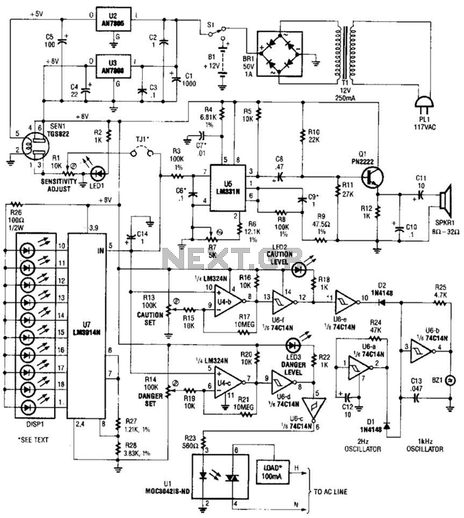
A gas sensor (TGS823 from Allegro Electronics, Cornwall Bridge, CT 06754) conducts in the presence of explosive gases. U5 is a voltage-to-frequency converter that produces a frequency proportional to the sensor conductance. The output frequency ranges from 100 Hz...

This board layout was created using the SOIC version of a PIC16F627A without drawing the usual schematic first. Most of the part values are etched on the Layout. The SIP resistor packs I used are 10k ohm, some experimentation...
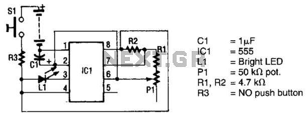
The circuit utilizes a 555 timer integrated circuit (IC) to drive an ultrabright LED. The output generated is a pulsing red light that can be focused using lenses. An ultrabright Stanley LED, which produces an output of 300 millicandela,...
National Instruments Multisim now features microcontroller unit co-simulation capabilities, enabling the inclusion of a microcontroller, programmed in assembly or C code, within SPICE-modeled circuits. The MCU functionality in Multisim allows students, educators, and professional users to program MCUs in...