
Joule Thief LED circuit 2

In electronic circuit design, adherence to standardized symbols and layout conventions is crucial for effective communication among engineers and technicians. A well-drawn schematic diagram serves as a visual representation of the circuit's functionality and interconnections, allowing for easier troubleshooting, collaboration, and documentation.
To create a circuit schematic, it is important to utilize established symbols for components such as resistors, capacitors, diodes, transistors, and integrated circuits. Each symbol conveys specific information about the component's function, orientation, and electrical characteristics. For instance, a resistor is typically represented by a zigzag line or a rectangular box, while a capacitor is shown as two parallel lines or a pair of curved lines, depending on the type.
The layout of the circuit should follow a logical flow, often from left to right or top to bottom, which helps in understanding the signal path and power distribution. Connections between components should be clearly indicated with lines, and junctions must be marked where multiple lines intersect, usually with a dot to signify a connection or a break to indicate that the lines do not connect.
Labeling components with reference designators (e.g., R1 for the first resistor, C1 for the first capacitor) further enhances clarity. Additionally, including values for each component, such as resistance in ohms or capacitance in farads, aids in the accurate reproduction of the circuit.
In summary, the proper use of universally recognized symbols and conventions in circuit schematics is vital for ensuring that the design can be easily interpreted and implemented by others in the field. This practice not only facilitates the design process but also promotes collaboration and reduces the likelihood of errors in circuit construction and analysis.Thats why you have to draw a circuit using a placement and CONVENTION that everyone recognises. 🔗 External reference
Related Circuits
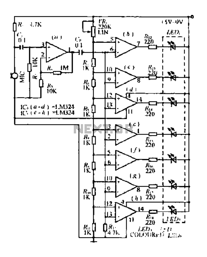
The condenser microphone pickup signal is processed by an integrated circuit (IC) where it is amplified and compared using a comparator circuit. The outputs from the comparators, designated as IC1, IC2, and IC3, provide voltage comparisons based on different...
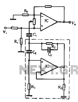
In the second equalization circuit connection method, it operates as illustrated in Figure 1-96. When the potentiometer wiper is moved to the inverting input terminal "a", the resonance impedance of the parallel combination of the feedback resistor RB reaches...
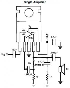
This is a simple mini audio amplifier circuit built around a single LM383 integrated circuit, along with several discrete components to support its operation. The circuit is capable of delivering approximately 7W of audio output. It can be constructed...
This is a simple proximity switch utilizing the IC 4049. The IC 4049 is a bipolar monolithic integrated circuit designed for metal detection systems and proximity sensing applications. It includes an oscillator formed by an external parallel resonant tank...
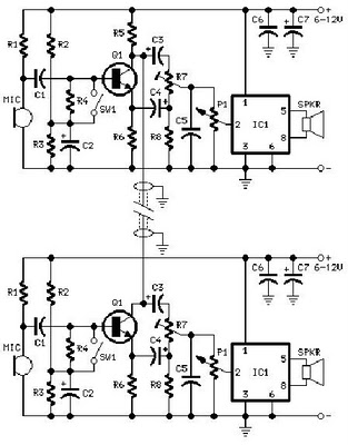
A project is proposed to construct a two-phone intercom system capable of functioning over a distance of up to 1 kilometer. The system will utilize the speaker of each phone to produce a ringing sound on the other end. The...
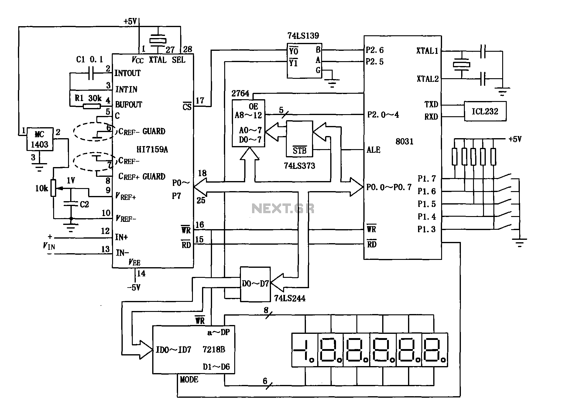
An intelligent digital voltmeter circuit utilizing the HI7159A, 8031 microcontroller, and various other components as illustrated in the figure. The internal circuit incorporates a successive cumulative integrator, digital zero function, low noise BIMOS technology, and other advanced features. In...