
Wireless Ir Security System

The schematic of this system can be divided into three primary sections: the IR transmitter, the IR receiver with RF transmission capabilities, and the RF receiver/beeper unit.
In the IR transmitter section, the two LEDs are arranged in such a way as to maximize the coverage area of the emitted infrared light. They are driven by a pulse generator circuit that modulates the LEDs at a specific frequency, creating a pulsed infrared beam. The modulation frequency is critical for ensuring reliable detection by the phototransistor in the receiver.
The IR receiver section includes a phototransistor that is sensitive to the specific wavelength of the emitted infrared light. This component is connected to an amplification circuit that increases the strength of the detected signal. When the beam is interrupted, the receiver's circuitry detects the drop in signal strength, triggering a comparator circuit that activates the RF transmitter. The RF transmitter then generates the 49.890 MHz carrier signal, which is modulated with a 490 Hz tone using an amplitude modulation technique.
The RF receiver/beeper unit is equipped with a superheterodyne receiver design that demodulates the incoming RF signal. The demodulation process extracts the 490 Hz tone from the carrier frequency. Upon successful detection of this tone, the unit activates a beeper or alarm, which serves as an alert mechanism for the user. The RF receiver is designed to operate within a certain range, enabling it to pick up signals from multiple transmitters, although it lacks the sophistication to identify which specific transmitter has triggered the alarm.
Overall, this system provides a reliable method for detecting intrusions and alerting users, leveraging both infrared and radio frequency technologies to achieve its objectives. It can be utilized in various applications, including security systems and automated monitoring setups, where unobtrusive detection is necessary. This system contains an IR transmitter, an IR receiver/RF transmitter, and an RF receiver/alert beeper. Two IR LEDs in the transmitter transmit a pulsed beam of invisible infrared light to the receiver, which contains an IR phototransistor. The phototransistor detects and amplifies the pulse-modulated IR beam. If the receiver section senses that the IR beam is momentarily interrupted by an object blocking the beam"s path, it triggers the transmitter, which outputs a 49.890-MHz carrier that is amplitude-modulated by a 490-Hz tone.
Upon receiving the 490-Hz amplitude-modulated carrier, the RF receiver/beeper unit sounds an alarm that alerts the user to the intrusion. The system is not limited to just one RF transmitter. A single RF receiver/beeper can be used to monitor any number of RF transmitters (or locations). However, the receiver/beeper unit cannot discriminate between different transmitter sites in multiple-transmitter systems.
Related Circuits
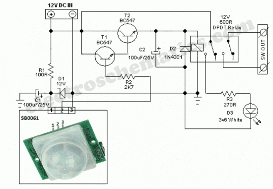
The SB0061 is a pyroelectric sensor module designed for human body detection. It integrates a PIR (Passive Infrared) detector with a Fresnel lens on a compact printed circuit board (PCB), along with an analog integrated circuit (IC) identified as...
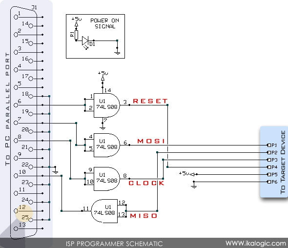
In-System Programming (ISP) allows for the serial programming of a microcontroller while it remains on the board, eliminating the need to remove the chip. This method provides a straightforward and cost-effective solution for programming and debugging microcontroller-based projects, whether...
The transmitter circuit for inductive headphones must be installed on a wall or ceiling, limiting their use outdoors. This is a significant drawback of inductive headphones. In contrast, infrared wireless headphones do not have this limitation; their flexible infrared...
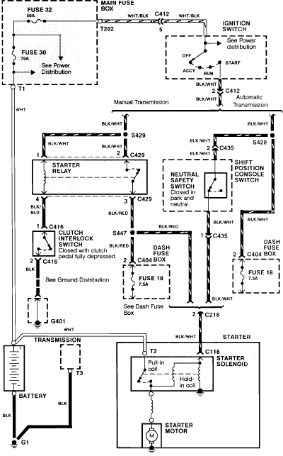
1990 Acura Integra Starting System Wiring Diagram. The 1990 Acura Integra starting system wiring diagram provides a visual representation of the electrical connections and components involved in the vehicle's starting system. This diagram is essential for understanding the layout and...

This circuit is an Automatic Gain Control (AGC) system designed for audio-frequency signals. AGC systems typically consist of three main components: an amplifier, a rectifier, and a controlled impedance. In this particular circuit, the functions of both the amplifier...
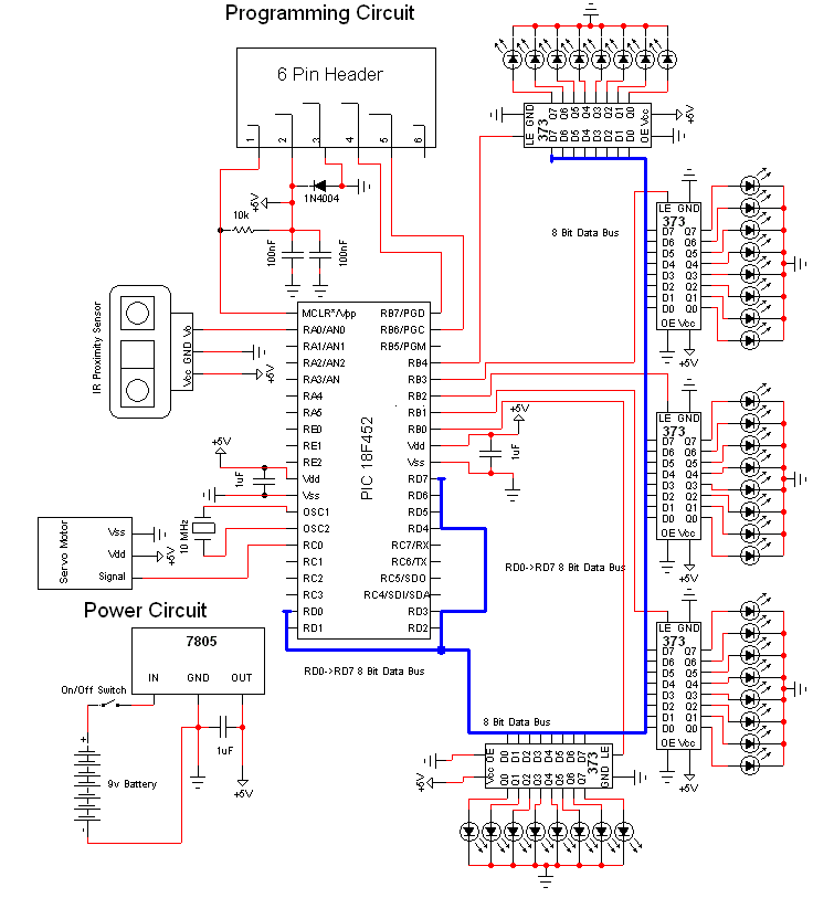
This document discusses a do-it-yourself alarm system utilizing the PIC18F452 microcontroller. It is a highly engaging project, although the schematic is quite complex. The project employs three main components to create the personal alarm system. The infrared (IR) proximity...