
WIRELESS MICROPHONE

An operational amplifier (op-amp) such as the 741 is commonly used in audio applications due to its high input impedance and low output impedance, making it ideal for amplifying weak signals from microphones. The gain of the op-amp is controlled by the resistor R12, which can be adjusted to set the desired amplification level for the audio signal captured by MIC1.
Once the audio signal is amplified, it is sent to the oscillator circuit, which is responsible for converting the audio signal into a frequency-modulated (FM) signal. This is achieved through the operation of transistor Q1, which acts as a switch or amplifier in the oscillator circuit. The use of a varactor diode (D2) is critical in this setup, as it allows the frequency of the oscillator to vary based on the audio signal input. The capacitance of the varactor diode changes with the applied voltage, which is influenced by the audio signal, thus resulting in frequency modulation of the oscillator output.
Inductor L1 plays a significant role in the oscillator circuit. Constructed from half a turn of #18 gauge wire on a half-inch diameter form, L1 contributes to the tuning and stability of the oscillator. The inductance value, combined with the capacitance of the varactor diode, determines the oscillation frequency, which is then modulated by the audio signal.
The final output is transmitted through a 12-inch whip antenna, which is designed to efficiently radiate the modulated signal into the surrounding environment. The length of the antenna is optimized for the frequency range of the oscillator, ensuring effective transmission of the audio signal over a distance. Overall, this circuit design effectively combines amplification, modulation, and transmission to create a functional audio transmission system.An op-amp IC (741) amplifies the audio signal from MIC1, and R12 controls its gain. Audio is fed to the oscillator circuit Q1 and related components. D2 is a varactor diode. Audio fed to D2 causes FM of the oscillator signal. L1 is 1/2 turns of #18 wire on a He" diameter form. The antenna is a 12" whip. 🔗 External reference
Related Circuits

This design circuit is for a stereo amplifier intended for a high-sensitivity stereo parabolic microphone, enabling the listening of distant sounds. Unlike typical parabolic microphones that are monophonic, this unit features a stereo audio path, resulting in more realistic...

This is a design circuit for an alarm. This circuit is intended for an anti-theft wireless alarm that can be used with any vehicle operating on a 6 to 12 volt DC supply system. A mini VHF FM radio-controlled...
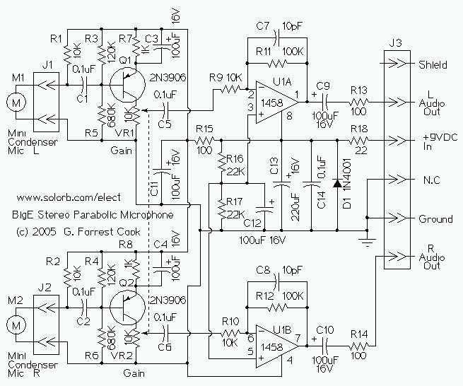
This device is a stereo amplifier for a high sensitivity stereo parabolic microphone. It can be used for listening to distant sounds. The Big-E can be used with headphones or as an audio source for a stereo tape recorder...
A 0 to 2 MHz frequency meter with a Minimum Mass Wireless Coupler, based on the ATMega8. Range to the Minimum Mass Base Unit is 10 to 15 cm. Since the frequency meter is battery operated, it can be...
The transmission circuit for inductive wireless headsets must be securely mounted on a wall or ceiling, limiting its outdoor usability, which is a significant disadvantage of inductive wireless headphones. In contrast, infrared wireless headsets utilize a compact infrared transmitter...
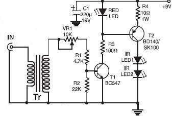
This wireless infrared (IR) headphones circuit project enables the transmission of audio signals through an infrared connection. The circuit consists of two main components: a transmitter and a receiver. Unlike radio frequency (RF) transmitters, both parts of this application...