
car anti theft wireless alarm circuit

The anti-theft wireless alarm circuit is designed to enhance vehicle security by utilizing a combination of RF communication and relay control mechanisms. The circuit operates within a voltage range of 6 to 12 volts DC, making it compatible with most vehicles. The transmitter, a mini VHF FM radio module, is discreetly installed in the vehicle and remains dormant when the vehicle is parked, conserving power.
In normal operation, the receiver, which employs the CXA1019 FM radio module, continuously monitors the frequency of the transmitter. When the transmitter is within range, the receiver outputs a clean signal, resulting in no audible noise. This state keeps transistor T2 in an off condition, preventing any activation of the relay driver transistor T3. The relay remains energized, ensuring that the alarm system is inactive, which is the desired state when the vehicle is secure.
In the event of theft, as soon as the vehicle is moved beyond the operational range of the transmitter, the communication link is severed. The CXA1019 begins to generate a hissing noise due to the lack of a coherent signal, which is indicative of a breach in the system. This noise is crucial as it is coupled to the relay switching circuit through an audio transformer, converting the audio signal into a form suitable for further processing.
The rectification and filtering stage, involving diode D1 and capacitor C8, is critical for converting the AC signals generated by the hissing noise into a usable DC voltage. This voltage is essential for turning on transistor T2, which in turn pulls the base of T3 to ground, effectively deactivating the relay. The relay's deactivation triggers the alarm system, alerting the owner of the unauthorized movement of the vehicle.
This circuit design not only provides a cost-effective solution for vehicle security but also illustrates the effective use of RF technology in alarm systems. The components used are widely available, making it an accessible project for hobbyists and professionals alike.This is a design circuit for alarm. This circuit is for an anti- theft wireless alarm can be used with any vehicle having 6 to 12 volt DC supply system. The mini VHF FM radio-controlled, FM transmitter is fitted in the vehicle at night when it is parked in the car porch or car park.
The receiver unit of the wireless alarm uses an CXA1019, a single IC-based FM radio module, which is freely available in the market at reasonable rate, is kept inside. This is the figure of the circuit. Receiver is tuned to the transmitter`s frequency. When the transmitter is on and the signals are being received by FM radio receiver, no hissing noise is available at the output of receiver.
Thus transistor T2 (BC548) does not conduct. This results in the relay driver transistor T3 getting its forward base bias via 10k resistor R5 and the relay gets energized. When an intruder tries to drive the car and takes it a few meters away from the car porch, the radio link between the car (transmitter) and alarm (receiver) is broken.
As a result FM radio module gene-rates hissing noise. Hissing AC signals are coupled to relay switching circuit via audio transformer. These AC signals are rectified and filtered by diode D1 and capacitor C8, and the resulting positive DC voltage provides a forward bias to transistor T2. Thus transistor T2 conducts, and it pulls the base of relay driver transistor T3 to ground level. The relay thus gets de-activated and the alarm connected via N/C contacts of relay is switched on. 🔗 External reference
Related Circuits

This device is designed to replace the original digital clock in a Fiat Ducato manufactured between 1992 and 1994. It is mounted above the inside rearview mirror. The original clock has limitations, including poor accuracy, a singular time display,...
This document describes a simple triac tester circuit that can also be utilized for testing silicon-controlled rectifiers (SCRs) and both PNP and NPN transistors. The circuit operates on 3V DC, which can be derived from a Zener diode combined...

This project involves connecting the positive terminal of the battery to the positive lead of the buzzer and the negative terminal of the battery to the negative lead of the buzzer. Typically, the positive lead of the buzzer is...

As environmental awareness increases, electric cars have become an essential part of people's transportation. Preventing electric car theft is a significant concern for owners. Various electric vehicle anti-theft locks have been developed; however, theft of electric cars continues to...
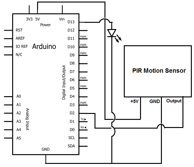
Once the motion sensor detects motion, the Arduino can be programmed to activate an LED, turn on a motor, sound a buzzer, etc. In this circuit, for simplicity, an LED will be turned on when the motion sensor detects...
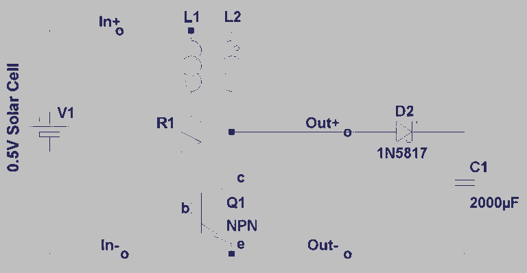
A steam engine-powered carousel project that utilizes the Joule Thief circuit. This project combines the classic charm of a steam engine with the innovative Joule Thief circuit, creating a unique carousel that operates efficiently. The steam engine serves as the...