
Wireless Power Charger Schematic

To build the circuit effectively, it is essential to adhere closely to the provided schematic diagram. This diagram serves as a visual guide, illustrating the connections between various components, including resistors, capacitors, diodes, and integrated circuits. Each component is labeled with its respective value and designation, ensuring clarity during assembly.
Begin by gathering all necessary components as indicated in the schematic. It is advisable to organize them systematically to streamline the assembly process. Pay attention to the orientation of polarized components, such as electrolytic capacitors and diodes, as incorrect placement can lead to circuit malfunction.
Once the components are prepared, start with the placement of the smallest components, typically resistors and small capacitors, onto the circuit board. This approach allows for easier handling and minimizes the risk of damaging larger components. Secure each component in place with solder, ensuring solid connections while avoiding cold solder joints.
After all components are soldered, inspect the circuit for any potential errors, such as misplaced components or solder bridges. A multimeter can be employed to test continuity and verify that connections are correct. Once the inspection is complete, power up the circuit gradually, monitoring for any unusual behavior.
In case of difficulties in identifying components or troubleshooting issues, consulting the schematic again or reaching out for assistance from knowledgeable sources can be beneficial. Proper documentation and a methodical approach will greatly enhance the likelihood of successful circuit assembly and functionality.To build it, just follow the schematic as shown. (If you need help, please, do not hesitate to message me!) If you`re having trouble identifying the.. 🔗 External reference
Related Circuits
The amplifier is based on the commonly used class-AB complementary power amplifier with compound pair output transistors. The system uses a TL074 quad opamp to drive the output transistors. As can be seen from figure 1, A2 is used to...
The fundamentals of crystals have not changed since this article appeared in a 1960 edition of Popular Electronics. The methods for growing, cutting, and packaging crystals have evolved significantly. Understanding their operation at the atomic level has also advanced...
Energy storage capacitors in even the smallest disposable camera flash powered by a 1.5 V AA battery can be hazardous under certain conditions. Line-powered devices, regardless of size, may present additional risks due to high power at high voltage...
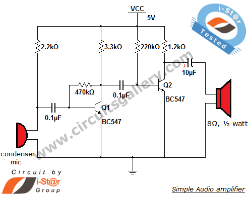
The output of the condenser microphone is coupled through a 0.1 µF coupling capacitor, which serves to eliminate DC components from the audio signal. Transistor Q1 is configured in a collector-to-base biasing mode, achieved with a 470kΩ resistor. This...
A current meter is employed to measure the current generated by a solar panel, exhibiting minimal power loss for currents within the 0-10A range. It also serves as a general-purpose DC current meter. The Gate Boost Solar Engine utilizes...
The described shunt-feedback configuration facilitates the straightforward incorporation of frequency-dependent networks, enabling a practical and unobtrusive switchable tilt control as an optional feature. When switch SW1 is in the first position, a gentle shelving bass boost and treble cut...