
Wireless Switch Circuit PCB

This wireless relay switch circuit utilizes the CA3140 operational amplifier, which is configured to amplify the small current changes induced by the phototransistor when it detects interruptions in the infrared beam. The infrared LED emits a continuous beam of infrared light, which is directed towards the phototransistor. When a hand or object interrupts this beam, the phototransistor's conductivity changes, resulting in a variation in its output signal.
The circuit includes a power supply, typically a battery or DC source, which powers the infrared LED and the operational amplifier. The phototransistor is connected to the input of the CA3140, which is set up in a comparator configuration. When the infrared light is uninterrupted, the phototransistor remains in a non-conductive state, and the output of the CA3140 stays low, keeping the relay in the off position. Conversely, when the beam is interrupted, the phototransistor conducts, causing the voltage at the input of the CA3140 to rise above a certain threshold. This triggers the output of the CA3140 to switch high, activating the relay and turning on the connected appliance.
The relay acts as a switch that can handle higher voltages and currents, allowing it to control various devices safely. Additional components such as resistors and capacitors may be included in the circuit to stabilize the operation and prevent false triggering from ambient infrared sources or noise.
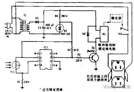
Overall, this wireless relay switch circuit offers a convenient and efficient means to control home appliances through simple hand gestures, enhancing user interaction and accessibility.The circuit diagram shown here is a very sensitive wireless relay switch that can be used to control the working of home appliances like flush system, hand dryer or else. The wireless switch described here needs no remote control for its working. You only want to move your hand between the infrared LED and photo transistor to control the device or
load. The circuit is built around an IC CA3140, IRLED1, photo transistor and other discrete components. The working of this circuit is very simple. In order to switch on the device or appliance you simply interrupt the infrared rays falling on the photo transistor through 🔗 External reference
Related Circuits
In this figure, S1 initiates the timing process, and once the timer is activated, toggling this switch will not impact the timing operation. S2 serves as the OFF switch located in the center; toggling this switch allows the timer...
The flash beam can be utilized to power remote control devices for AC power applications. A key feature of this device is its memory function, which allows it to supply power continuously. Upon the second activation, the power will...
The figure illustrates a bilateral band modem circuit utilizing the NE561B component. The input modulating signal operates at a loading frequency of f0 = 1 MHz. When the AM modulation signal is applied to the input terminal of the...

P1 47K logarithmic potentiometer; P2, P3 47K linear potentiometers; R1, R3, R5 4.7K 1/4W resistors; R2 22K 1/4W resistor; R4 1M 1/4W resistor; R6 1.8K 1/4W resistor; R7 560Ω 1/4W resistor; C1, C4, C5, C7 10 µF 63V electrolytic...
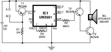
The UM3561 integrated circuit can be utilized to design various alarm systems with minimal electronic components. This UM3561 alarm electronic project requires only a few electronic parts and operates on a simple 3 volts DC power supply. The UM3561 is...
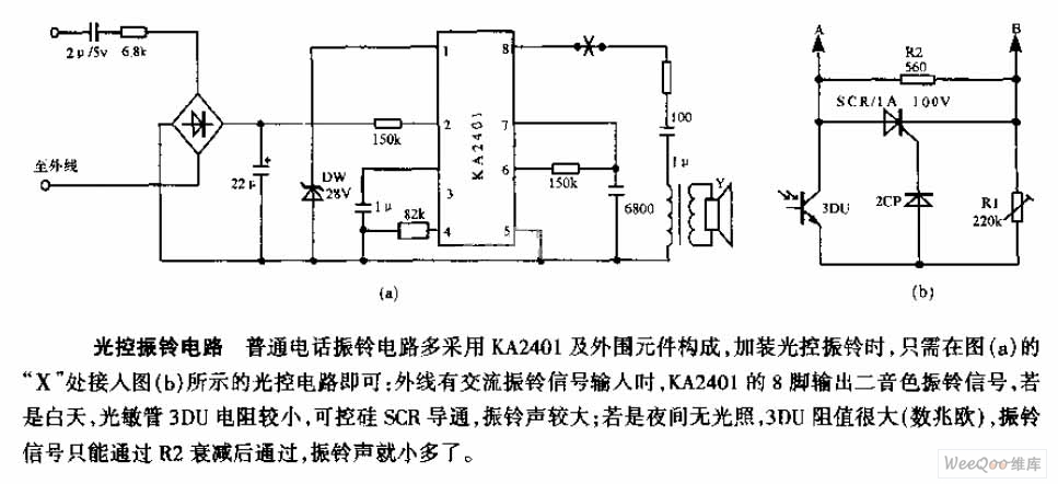
The average telephone ring circuit consists of the KA2401 integrated circuit and its associated peripheral components. To integrate a light-operated ring circuit, connect the designated part X in the provided diagram (picture a) to the light-operated circuit shown in...