
Wiring schematic for 2005 636 Kawasaki

The electrical system of the motorcycle in question consists of several critical components that interact to facilitate engine operation. The starter motor is responsible for initiating the engine's crankshaft rotation, while the fuel pump ensures that fuel is delivered to the engine for combustion. The presence of a blown tail lamp fuse when the starter button is pressed indicates a possible short circuit within the wiring harness, which could lead to excessive current draw, causing the fuse to blow.
When diagnosing this issue, it is essential to inspect the wiring harness for any visible signs of damage, such as frayed wires or poor connections. A multimeter should be utilized to check for continuity in the starter circuit and the fuel pump circuit. This includes verifying the integrity of the starter relay and the ignition switch, as these components can also contribute to starting issues.
The "FI" light on the instrument cluster suggests that there may be an active fault in the fuel injection system, which could be related to the fuel pump not activating automatically. It is advisable to investigate the connections to the fuel pump and any associated relays or fuses. If the fuel pump operates correctly when manually jumped, the issue may lie in the control circuit rather than the pump itself.
In the absence of a schematic, one approach is to create a simple diagram based on the layout of the wiring harness and the known working conditions of each component. This can aid in isolating the fault and determining the necessary repairs. Once the schematic is available, it will provide a comprehensive overview of the electrical system, allowing for more efficient troubleshooting and resolution of the issues present.I removed the entire setup from a bike awhile back and it ran then, and also ran about a year ago in the engine stand that it`s currently mounted in now. This afternoon I went to start the thing up to test things out before selling it off and hit a glitch.
Pressing the starter button on the controls caused the tail lamp fuse to blow and the starter did not spin over. Seems like an obvious short that I need to trace. I did some searching for a diagram/schematic but can`t find anything for the 05/06 DFI bikes. Is there such a diagram online that can be downloaded I went to the dealer for a FSM, which I can order but it wouldn`t be in until next week and I was hoping to try and find somethign tonight. I have the entire harness/electrical system laying here on my living room carpet ready to diag if I can just get a schematic The starter turns over if I manually jump it.
I also noticed that the fuel pump does not activate, but it does work if I manually jump that as well. with a sub harness. Everything else seems to work fine. throttle and exhaust actuator cycle when you turn the key on, cluster illuminates just fine, etc. I did notice the "FI" light was on in the cluster, but I cannot remember if that remained on when until the engine started or not(similar to a check engine light in a car)
🔗 External reference
Related Circuits
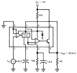
The LM2917 IC chip is specifically designed as a Frequency to Voltage Converter. It requires only a few external components for its operation. The datasheet for the LM2917 IC includes several application examples of the Frequency to Voltage Converter....
The 5 V from USB appears to be powering the LED on the laptop power brick. Therefore, even when the power brick is turned off at the wall outlet, the LED remains illuminated. When the USB is unplugged, the...
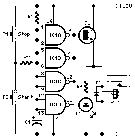
This timer is designed to automatically switch off a portable radio after a set period, allowing users to relax without worrying about battery drain. Resistor R1 and capacitor C1 create a long time constant. When switch P2 is momentarily...
This chapter presents a variety of circuits for basic power supplies, including both line-powered and inverter types, some of which feature regulators, modulation inputs, and additional functionalities. Several circuits have been reverse-engineered from actual commercial products, and others, designed...
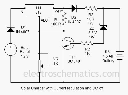
This is a solar charger circuit designed to charge Lead Acid or Ni-Cd batteries utilizing solar energy. The circuit captures solar energy to charge a 6-volt, 4.5 Ah rechargeable battery for various applications. It includes voltage and current regulation,...
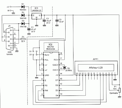
To convert a standard LCD interface from parallel to a serial interface model, a microcontroller or a dedicated circuit such as the MIC 702 from Mictronics can be used. This circuit is specifically designed to transform the parallel interface...