
Wiring up to the AN2131
The AN2131 chip is a microcontroller designed for handling input and output operations, particularly in embedded systems. The integration of a crystal oscillator is critical for providing a stable clock signal, ensuring the microcontroller operates at the desired frequency. Power regulators are essential for supplying the appropriate voltage levels to the AN2131 and supporting components, maintaining operational integrity.
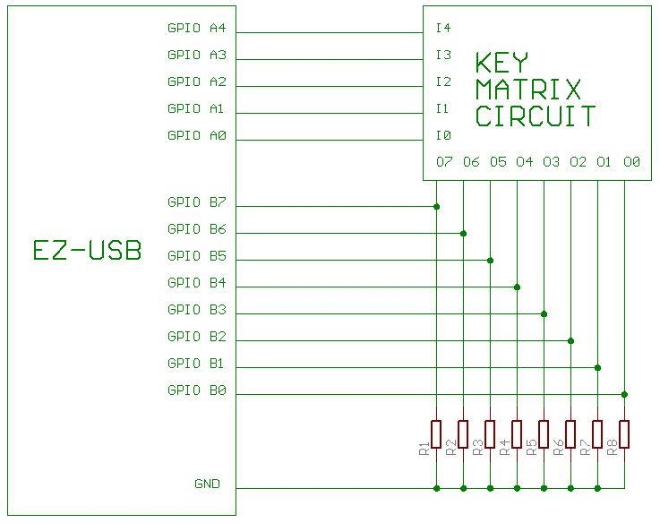
The key matrix serves as an interface for user input, where each key press corresponds to a unique signal. The GPIO ports of the AN2131 are configured to read these signals. However, without proper termination, floating inputs can lead to erratic behavior, such as keys appearing to be continuously pressed. The implementation of pull-down resistors effectively mitigates this issue by ensuring that the GPIO pins are pulled to a low state when not actively driven high by a key press.
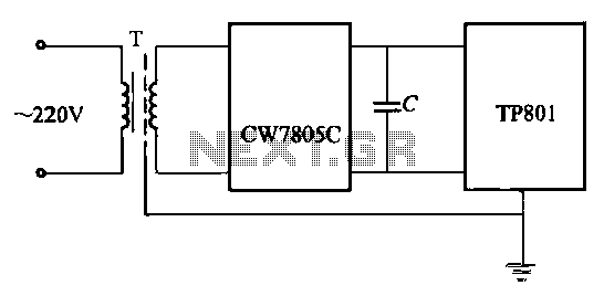
The choice of pull-down resistor values, ranging from 320 ohms to 1000 ohms, indicates a consideration for both power consumption and response time. Lower resistance values will provide a quicker discharge of residual charge but may draw slightly more current when the keys are pressed. Conversely, higher resistance values reduce current draw but may result in slower response times. The final circuit diagram would illustrate the connections between the AN2131, the key matrix, and the pull-down resistors, ensuring clarity in the design and functionality of the circuit.It`s just a AN2131 chip with the required support circuitry - crystal oscillator, power regulators etc. First I took the inputs and outputs of the key matrix and wired them to the GPIO ports of the AN2131.
This was just a matter of plugging the whole lot into some protoboard. This didn`t work too well, as the keys would get "stuck" often. This is because an unconnected chip leg can "float" between on and off due to the residual charge held in the wire. The solution is to add pull-down resistors which allow this residual charge to flow to ground when the key is released. I added one to each input of the circuit. I used a variety of spare resistors from the junk box 320 ohms to 1000 ohms. This is the final circuit diagram: 🔗 External reference
Related Circuits
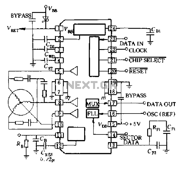
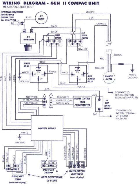
A8902 is a typical application wiring diagram. After a system failure signal from the delay island and CB 11 feeds into the motor brake, the system stops functioning until the RESET signal arrives, at which point the motor restarts. The...
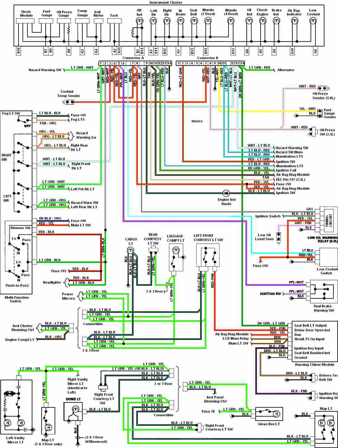
Automotive diagram for the instrument cluster of the 1987-1993 Ford Mustang (Third Generation). The instrument cluster for the 1987-1993 Ford Mustang serves as a critical interface for the driver, providing essential information about the vehicle's operational status. This cluster typically...
1994 Mercury Topaz Instrument Cluster Illumination Wiring Diagram. The 1994 Mercury Topaz instrument cluster illumination wiring diagram provides a detailed representation of the electrical connections and components responsible for the lighting system within the instrument panel. This diagram is essential...
Mercury, Oldsmobile, Plymouth, Pontiac, muscle cars, and antique classic car wiring diagrams are continuously being added to this site. The wiring diagram for the Porsche 911L engine from the 1968 model has undergone changes since the original scheme. For...
High-precision voltage regulator, isolation transformer with the correct wiring, and low-pass filter to enhance the electrical noise immunity of the source portion. The wiring in Figures 20-48 and 20-49 is illustrated in the figures. Chokes (L1, L2) should have...
This is the complete wiring diagram for the 1997 Honda CR-V. It includes wiring diagrams for each electrical module of the Honda CR-V, such as the Rear Wiper/Washer Circuit, Front Wiper/Washer Circuit, Warning System Circuits, and the Supplemental Restraint...