
1994 Mercury Topaz Instrument Cluster Illumination Wiring Diagram

The 1994 Mercury Topaz instrument cluster illumination wiring diagram provides a detailed representation of the electrical connections and components responsible for the lighting system within the instrument panel. This diagram is essential for troubleshooting and repairing issues related to the illumination of the dashboard gauges and indicators.
The wiring diagram typically includes the following components:
1. **Power Source**: The diagram indicates the source of power, usually from the vehicle's battery or ignition switch, which supplies voltage to the illumination circuit.
2. **Dimmer Switch**: A dimmer switch is often integrated into the circuit, allowing the driver to adjust the brightness of the instrument cluster lights. The wiring diagram shows how this switch connects to the power source and the illumination bulbs.
3. **Illumination Bulbs**: The diagram details the placement of the illumination bulbs within the instrument cluster. It specifies the type of bulbs used and their connection points to the circuit.
4. **Ground Connections**: Proper grounding is crucial for the functionality of the lighting system. The wiring diagram illustrates the ground points that complete the circuit, ensuring that the bulbs operate correctly.
5. **Color Codes**: The wiring diagram may include color codes for the wires, aiding in the identification of each connection and facilitating easier repairs and modifications.
6. **Additional Components**: Depending on the complexity of the circuit, additional components such as fuses, relays, or connectors may be depicted, providing a comprehensive view of the instrument cluster's electrical system.
Understanding this wiring diagram is critical for automotive technicians and DIY enthusiasts when diagnosing lighting issues or performing upgrades to the instrument cluster in the 1994 Mercury Topaz. Proper interpretation of the diagram ensures accurate repairs and maintenance of the vehicle's electrical system.1994 Mercury Topaz Instrument Cluster Illumination Wiring Diagram. 🔗 External reference
Related Circuits
The tank circuit consisting of capacitor C2 and inductor L1 is utilized to tune the transmitter. The antenna is coupled to the transmitter through capacitor C3 and can be either a telescopic antenna or a length of hookup wire....
An FM tracer was developed using the LM3909 integrated circuit (IC) along with several supporting components. This 1.5V FM tracker serves as an indicator of revenue sources by emitting a signal through an LED. The FM tracking circuit operates...

The tester comprises a rectifier circuit and a multivibrator circuit. The alternating current (AC) voltage is half-wave rectified by diode D1 and stored in capacitor C1. Resistor R1 is employed to limit the current through D1 to a safe...
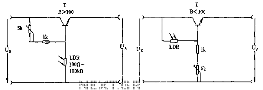
The circuit depicted involves a photoresistor (LDR) connected to a transistor, which operates at either a high or low level based on light conditions. The amplification factor of the transistor is 100, which is adequate for the application. The...

A simple burglar alarm circuit diagram and schematic. This can be used as an anti-theft alarm by attaching the burglar alarm circuit to window foil. The burglar alarm circuit is designed to provide a basic security solution for residential or...

A bridge input circuit utilizing a phototransistor BPY62 and a power operational amplifier is capable of controlling power loads up to 8.5 kW. It features a voltage divider composed of two 10 kΩ resistors, creating a midpoint connection. The...