
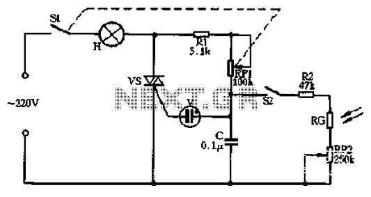
With triac light control lamp 1

The described circuit operates as an automatic light control system, utilizing a photoresistor and resistors to regulate the illumination of a lamp based on ambient light conditions. The photoresistor (RG) is sensitive to light levels; during the day, it maintains low resistance, which keeps the voltage across the lamp (H) insufficient for illumination. This ensures energy efficiency by preventing unnecessary lighting during daylight hours.
In low-light conditions, the resistance of RG increases, which raises the voltage across the LED indicators. LED2 is activated during the positive half-cycle of the AC supply, serving as a visual indicator that the circuit is functioning correctly. When the AC supply shifts to the negative half-cycle, LED1 lights up, indicating that the SCR is ready to be triggered. The SCR's control electrode receives the necessary voltage from the LEDs, allowing it to conduct and thus energize the lamp (H).
The inclusion of the variable resistor (RP) enables fine-tuning of the circuit's sensitivity, allowing users to set the threshold at which the lamp will turn on based on the ambient light level. This feature is particularly beneficial in varying environmental conditions, ensuring that the lamp operates optimally according to specific user requirements. The overall design is efficient for applications such as garden lighting, streetlights, or any system where automatic light control is desired based on natural light availability.And the section of the circuit is similar, with the solid photoresistor RG fixed resistor Rl also form a voltage divider. Light-emitting diodes LED1, LED2 here doubles as a pow er indicator, fork for rectifying trigger. When the positive half-cycle alternating current in the positive case of the negative, LED2 is turned on (of course, at night) to vs provide positive trigger current, when the alternating current in the negative at positive negative half-cycle, LED1 is turned on (the same kind should be at night ) to provide reverse trigger current vs. During the day, natural light is strong. RG showed low resistance, low partial pressure, vs can not be opened, the lamp H does not shine. Only nightfall, the partial pressure is higher, the alternating voltage applied to LED1 and LED2 vs SCR control electrode, so vs open, lights on the light H normal light.
RP can be used to adjust the light control sensitivity.
Related Circuits
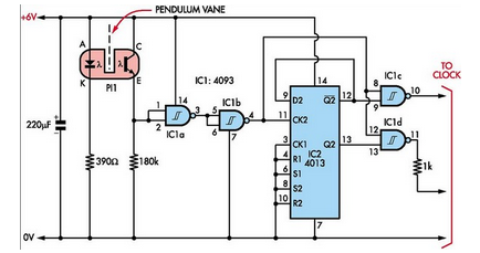
Here is how to build a pendulum-controlled clock that can be made very accurate. Retro? Yes, but it is an interesting project nonetheless. You will need a specific set of components. A pendulum-controlled clock is a mechanical timekeeping device that...
A good performance is achieved with a two-wire connection for a double touch switch that can function even if there is a break in the left part of the line. This switch is designed for general lighting control, such...
Circle S2 is a stable automatic light switch. When S2 is open, the entire circuit operates as a subsection II SCR stepless presentation dimmer, omitting the high-frequency filter circuit. The trigger diode switch activates a neon indicator bulb (V),...
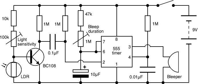
The circuit detects a sudden shadow on the light sensor and activates a bleeper when this occurs. It is designed to ignore gradual changes in brightness to prevent false alarms. The bleeper operates for a brief duration to conserve...
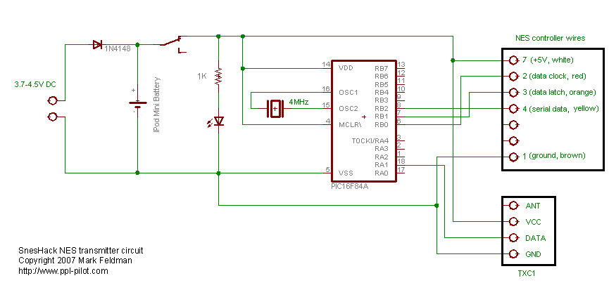
The NES version of this modification closely resembles the SNES version, and it is advisable to review that article first for a general understanding of the assembly of these controllers. The primary component required is an original NES controller,...
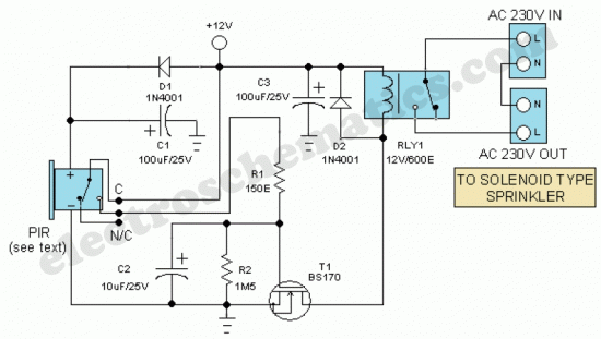
The Motion Sensor Switch circuit is an automatic water sprinkler controlled by a motion sensor, with the option to incorporate an alarm or light function. Before starting the construction, it is advisable to contact a local electronics component vendor...