
Press light switch double circuit 7

The circuit operates effectively as a touch-sensitive lighting control system, utilizing a two-wire setup to facilitate functionality even in the event of a line interruption. The primary components include a neodymium tube for rectification, crystal thyristor for switching, and transistors for amplification and control.
The neodymium tube (VD1 to VD-1) serves as the rectifier, converting AC voltage to a suitable DC voltage for the rest of the circuit. The thyristor (VT3) acts as the main switching device, which is triggered by the control transistors (VT1 and VT2). When the user touches the M1 electrode, the resulting induced current activates VT2, allowing it to conduct. This conduction triggers the thyristor VT3, which then powers the connected lamp.
The design includes a feedback mechanism where touching the M2 electrode causes current to flow to VT1, enabling it to conduct and discharge the stored charge from the capacitor. This rapid discharge results in the thyristor losing its trigger current, effectively turning off the lamp.
To ensure reliable operation, the circuit incorporates anti-interference measures to mitigate the effects of voltage fluctuations that could lead to unintended activation or deactivation of the lighting system. The choice of components, including silicon diodes and a unidirectional thyristor, is critical for maintaining performance and reliability.
The installation of this circuit requires careful attention to wiring, particularly the connection of the 220V AC mains phase and neutral line. Incorrect wiring may result in malfunction or failure to operate. The circuit is designed to handle a load of up to 100W, making it ideal for incandescent bulbs and small lighting applications, providing a convenient and efficient solution for touch-sensitive lighting control.A good performance is a two-wire connection of double touch off indiscriminately even a broken line in the left part of the line for the general lighting, flowers portion of li ght control switch, Ml to open cockles contact patch. M2 is against the light touch H. A neodymium tube V D1 ~ VD-1, crystal thyristor switch VT3 composed calling road, back to the routing control transistor VT1 and VT2 and the like, usually, product thyristor V113 in a pod off-state, electric E not bright. 220V AC by V [) L - VD-1 rectifier, R. And R. Points m, in C, Liduan gravity of about + sv electric generous, when manpower touch -r Ml electrode sheet, the induced current unravel human foot, into VT2 base, so VT/conduction.
[Namely through the stored charge to discuss VT2 (1 bleed so (1 ends get i from the voltage, is applied to the well through the R * f J pole of the thyristor VT3 make VT3 conduction, lamp was lit by the value of R is small, V r {turned its gate leakage current to be charged by R. C., so people leave to electric set piece fn, C. A terminal voltage Ding unchanged the lights remain lighting state electronic switch that is in the on state when the lamp needs Ge, only suddenly to touch the M2 electrode sheet, current flows through the human body sensors Rv injection VTi base so quickly VT1 conduction, then C storage VT1 discharge charge through discussion, so that both ends of the voltage drop quickly F, VT3 lost trigger current.
That is when the pods break alternating current passes through zero, E lights off, the electronic open-yan in the fire status .C. the role of anti interference can be prevented supply voltage fluctuations caused by malfunction Iseki VT1, VT2 on 9 011,9013 punishment, such as silicone NP] diodes require liver 7ceo 25V, mouth 100.VT3 type using ICR100 8,2N656j past small plastic unidirectional thyristor other components no special special requirements for wiring, 220V AC mains phase, the zero line must be connected shown in Figure F, otherwise the circuit not being normally work, this phase into Ji curse electrical wiring connection is in line with norms curse of the present Tr cylinder carrying capacity is mainly composed.
VT3 and VDI - VD4 current capacity decisions, illustrating the data load power at 100W or less, and the load is appropriate incandescent bulbs, small cargo sensual apply.
Related Circuits

A general-purpose hobby circuit for a simple light fence security beeper is presented here. This circuit can be utilized as a door alarm, gate alarm, pathway alarm, and more. It can be powered by any 12 Volt DC power...
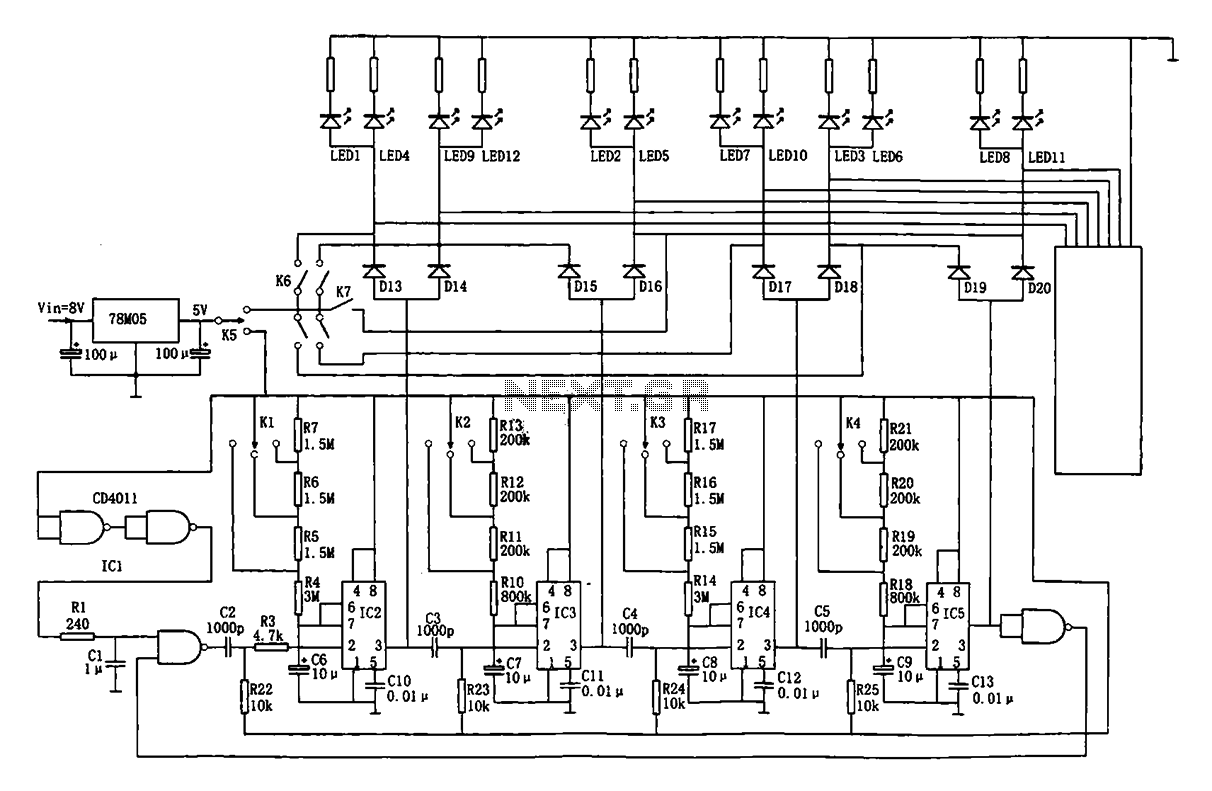
This document describes an automatic traffic intersection light control circuit. It features four monostable delay circuits, which consist of four 555 timer integrated circuits (IC2 to IC5) and several RC components interconnected. An 8V input voltage is regulated through...
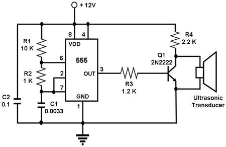
The circuit utilizes a 555 timer integrated circuit (IC) configured as an astable multivibrator, which generates a continuous signal at a specific frequency as long as its reset pin (pin 4) is held high. The ultrasonic transducer employed in...
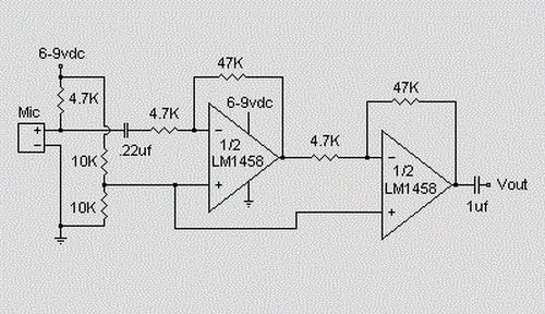
This is a simple preamplifier circuit designed for an electret condenser microphone, utilizing an LM1458 dual op-amp integrated circuit (IC). The circuit amplifies the audio signal from the condenser microphone, allowing it to be used as an input for...
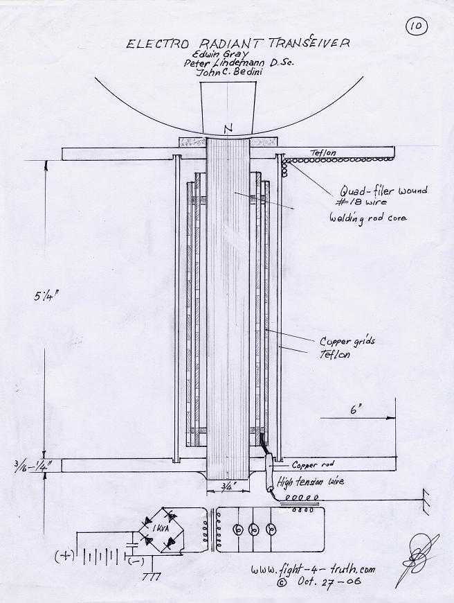
The power is all in the timed switching process. There are two main principles I use of switching the radiant energy the John Bedini way. First, the SG/SSG, Icehouse unidirectional circuit or John Bedini Monopole with the School Girl...
The clock is based on the PIC16F877 microcontroller from Microchip Technology Inc., which performs all of the logic necessary to decode the MSF signal and display the time on twelve 7-segment displays. The circuit design incorporates the PIC16F877 microcontroller, a...