
With TWH9248 9249 an auto lighting

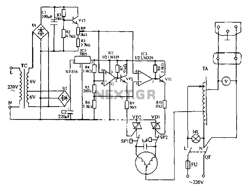
The described circuit is designed for automatic lighting control using a microwave detection system. The 220V AC input is first converted to a lower voltage using a CL buck converter, ensuring efficient power management. The VDI rectifier converts the AC voltage to DC, while the VD2 regulator stabilizes the output voltage to 12V DC, which powers the entire module A2. The filter capacitor (C2) smooths the output, ensuring stable voltage for sensitive components.
Module A2 incorporates an internal regulator that steps down the 12V to a 6V output, which is necessary for the operation of the TWH9249 gate control terminal. The sensitive resistor (RG) plays a critical role in controlling the gate of the TWH9249, allowing for the modulation of the signal based on the 6V output. This setup is essential for enabling the automatic light control feature.
The circuit's functionality is particularly notable during nighttime or low-light conditions when it detects movement. The microwave detection system works by emitting microwave signals and analyzing the echoes reflected back from any moving object, such as a human body. Upon detecting movement, the internal processing circuit at module A2 generates a delay signal that activates the solid-state relay (TAC108), which in turn powers the lamp (H). This provides immediate illumination in response to detected motion.
The delay mechanism ensures that the lamp does not turn off immediately after the motion ceases, allowing for a grace period during which the light remains on. This feature is designed to enhance user convenience, as it caters to brief movements without causing the lamp to flicker or turn off unexpectedly.
Furthermore, the inclusion of a potentiometer (RP) allows for fine-tuning of the detection sensitivity, enabling the user to adjust the system based on environmental conditions or specific requirements. This flexibility ensures that the circuit can be adapted for various applications, making it suitable for both residential and commercial lighting solutions. Overall, this circuit exemplifies a practical application of modern electronic design principles in creating an efficient and user-friendly automatic lighting system.220V AC by Cl buck, VDI rectifier, VD2 regulator and filter capacitor C2, output stable 12V DC voltage for use module A2, Al through internal A2 6V regulator outputs in 6V DC v oltage. Sensitive electrical resistor RG connected across TWH9249 gate control terminal R 6V voltage output terminal B, the circuit has an automatic light control function, the circuit will be blocked during the day does not work, H lamp is not lit, at night or when comparing light dark circuit that is able to lift the blockade restored to normal operation. When the body moves within the detection range, the module receives a microwave transmitter and the microwave echo reflected from the body compared to the more, the internal processing circuit by O terminal A2 output a delay signal to the solid state relay TAC108 turned on, the lamp H namely lit.
As the human body or human remains absolutely motionless after the departure, after the delay signal lamp goes out. If people move back, the lamp H will continue to light up. Circuit potentiometer RP can be used to adjust the detection sensitivity.
Related Circuits
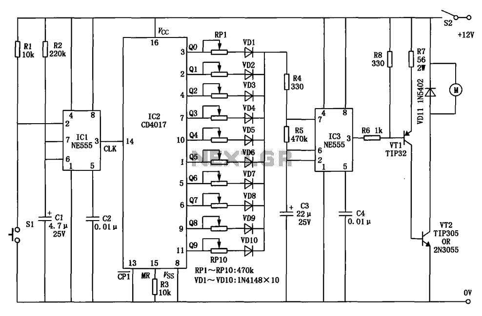
The circuit for a car wiper speed controller allows for adjustable wiper speed, ranging from one to ten cycles per second. This feature enables flexibility in operation and contributes to energy efficiency. The car wiper speed controller circuit typically employs...
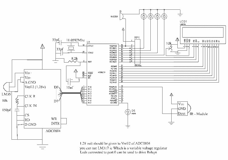
This circuit measures temperature in Celsius scale and displays it on an alphanumeric LCD screen. When temperature rises to 40°C, an alarm is activated and at the same time a relay is also activated which drives a fan to...
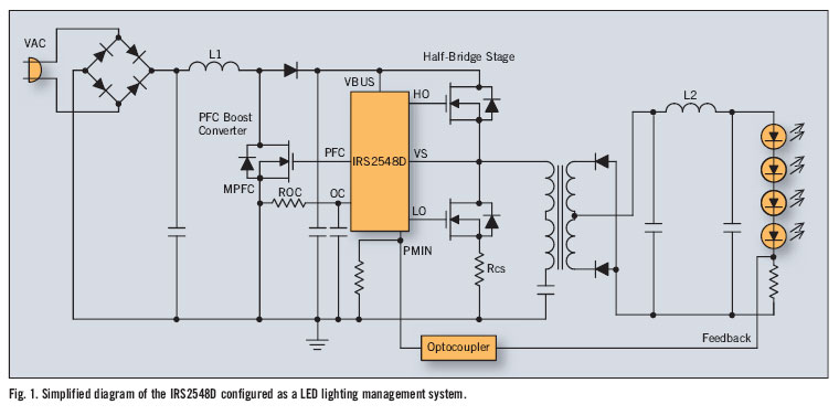
There is significant sensitivity to operating costs when managing high-powered commercial lighting. In these applications, there is a heightened focus on energy efficiency and AC line power factor, as these parameters influence operating expenses. Electric utilities impose additional charges...
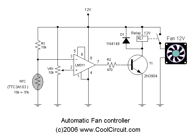
Automatic fan control circuit. This circuit turns a 12V DC fan or CPU fan on or off based on temperature readings. The temperature can be adjusted using VR1. The automatic fan control circuit operates by monitoring the temperature of...

The Project presented here waters your plants regularly when you are out for vocation. The circuit comprises sensor parts built using op-amp IC LM324. Op-amps are configured here as a comparator. Two stiff copper wires are inserted in the...
Automatic AC voltage regulator circuit The automatic AC voltage regulator circuit is designed to maintain a stable output voltage despite fluctuations in the input voltage. This circuit is essential for protecting sensitive electronic devices from voltage variations that can lead...