
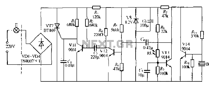
Automobile wiper speed control circuit diagram

The car wiper speed controller circuit typically employs a combination of resistors, capacitors, and a microcontroller or timer IC to manipulate the wiper motor's speed effectively. The core of the circuit often includes a pulse-width modulation (PWM) signal generator, which adjusts the duty cycle of the voltage supplied to the wiper motor. By varying the duty cycle, the average voltage and current supplied to the motor can be controlled, resulting in different speeds of operation.
In practical terms, the circuit may include a potentiometer that allows the user to manually adjust the wiper speed. This potentiometer is connected to the input of the microcontroller or timer, which interprets the resistance value and adjusts the PWM output accordingly. The wiper motor is then driven using an H-bridge configuration to allow for direction control, enabling the wipers to operate in both the forward and reverse directions if necessary.
The energy-saving aspect of this circuit is realized through the PWM technique, which reduces the average power consumption compared to a simple on/off control method. As the duty cycle is decreased, the wiper motor receives less power, thus conserving energy while still maintaining adequate performance.
Additionally, the inclusion of a feedback loop may enhance the system's response to varying conditions, such as rain intensity. By incorporating a rain sensor, the circuit can automatically adjust the wiper speed based on the amount of moisture detected on the windshield, providing optimal visibility and safety for the driver.
Overall, the design of the car wiper speed controller circuit emphasizes flexibility in operation, energy efficiency, and adaptability to environmental conditions, making it a valuable component in modern automotive systems. Circuit car wipers speed controller is shown in Fig. It can easily shake wiper speed between every second to ten times per second for any change, flexible and energy saving.
Related Circuits
A modified piezoelectric ceramic acoustic-electric transducer is utilized to create a sound and light control system for a stairway walkway with a delay lighting switch. The circuit structure is relatively simple, consisting of diodes VD1 to VD4 and a...

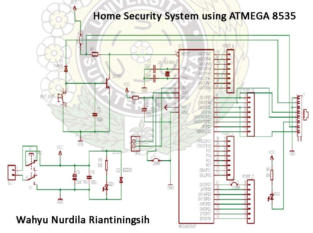
The schematic includes programmable AVRs. For other members of the AVR family or additional programmable ICs compatible with Ponyprog, there is a J1 connector (CON10) that facilitates hardware expansion of the programmer. Additional information about compatible ICs can be...
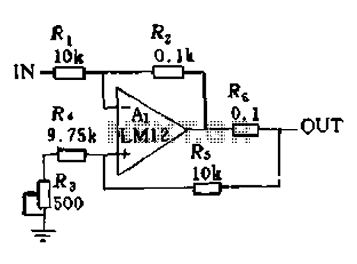
In a servo system, the current drive connection is frequently utilized. The output current (IOUT) is proportional to the input channel number (y). Using the current drive mode can mitigate issues caused by the motor's large inductance, which induces...
The Atmega 8535 Color Conversion to Frequency project utilizes instrumentation technology to recognize colors, also known as a color sensor, which is essential in various industrial applications. This sensor has multiple uses, ranging from the paint industry to satellite...
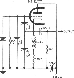
To update the fundamental oscillator circuits, simply replace the transistors with tubes. Alternatively, if one owns a vintage vacuum tube radio, it may be of interest to learn about historical practices. In general, the foundational principles of electronic circuits...
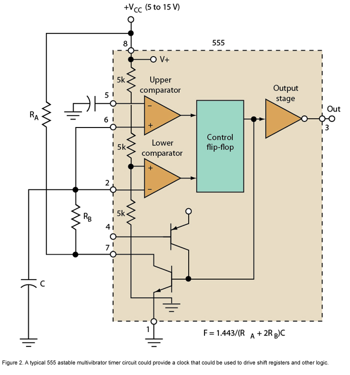
Micro or analog? These days, it is becoming increasingly challenging to make a choice. The 555 timer has long been regarded as a benchmark for flexibility. How does it perform today? The 555 timer IC, originally introduced in 1972, remains...