
X10 wireless transmitter
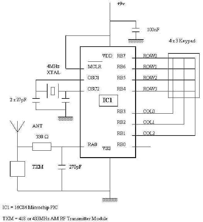
The electronic schematic for this RF transmitter unit will involve several critical components and connections. The PIC 16C84 microcontroller will serve as the main processing unit, controlling the output data stream through PORTA (specifically RA0) to the TXM module. The TXM will require a stable power supply, typically sourced from the same 9-volt battery used for the microcontroller. The output from RA0 will pass through a 330-ohm resistor to limit current and protect the TXM. The 270 pF capacitor will be connected in parallel with the power supply of the TXM to filter out any high-frequency noise, ensuring stable operation.
For the keypad interface, PORTB will be configured to read the inputs from the 4x3 matrix keypad. The upper four pins (RB7-RB4) will be set as input pins, while the lower four pins (RB3-RB0) will output signals to activate the rows of the keypad. This arrangement allows the microcontroller to detect which key is pressed based on the combination of input and output states. The internal pull-up resistors on the input pins will facilitate reliable key detection without the need for external resistors.
The antenna, a simple wire element, will be connected to the output of the TXM module, ensuring effective transmission of the RF signals. The design should also include considerations for housing the components, ensuring that the antenna is appropriately positioned for optimal range and performance. Overall, the schematic will provide a clear representation of the connections and components required to successfully implement the RF transmitter unit within the existing X10 home automation system.My present system is a dedicated 486 running Homeseer software. The hardware consists of a CM11A computer to X10 interface and a number of appliance and lamp modules. I also have a homebrew IR system that links the computer to my VCR, HIFI and TV. The "human" input to the system is via a Marmitek hand held controller which in addition to having IR learning capability can also send X10 commands via an RF signal at 418MHz.
These signals are picked up by a TM12U RF to X10 unit (the Euro version of the RR501) and sent via the mains wiring to the Homeseer program from the CM11A. Wishing to further expand my system, I decided to see if I could build a RF Transmitter unit that would communicate with the TM12U and allow me more inputs into my X10 system.
My first stop was an article by Edward Cheung Ph. D. on "Data format for X-10 wireless units". This gave me an idea of what the protocol for the RF data transmission should be. However I decided to check it out with my set up as the article was based on an RT-504 not a TM12U. Using a scope to look at the output from a 418MHz receiver I observed that the format was basically as described, however it had one subtle difference. Instead of 32 "1" samples per frame it had 33. I don`t know why! Being familiar with PIC microcontrollers, and having already used them for a number of remote control applications they have proven to be an excellent choice yet again.
Central to the unit is a PIC Microchip type 16C84. This is an 8 bit microprocessor with separate internal busses for memory and data. It has an internal divide by 4 connected between the oscillator and the internal clock bus. This makes instruction times easy to calculate if one uses a 4MHz crystal. Each instruction cycle is then 1uS. 13 I/O pins are available each with individual directional control. These are defined as PORTA (RA0-RA3) and PORTB (RB0-RB7). In this circuit only one PORTA pin is used (RA0). The output data stream comes from this pin and via a 330 ohm resistor drives TXM. The 270pF capacitor is for RF decoupling. TXM is an AM RF Transmitter Module comprising a two terminal high stability oscillator designed for short range data/remote control applications at 418 or 433MHz. These modules are ideal for the RF - X10 applications as they need the minimum of extra components to function.
In the UK the modules are available from Maplins Part # NV08J. For US units, a part that operates at 310MHz is needed. The antenna is a short length of wire fitted inside the plastic box that holds the unit. PORTB is used to read the keypad. This is also from Maplins (Part # JM09K) this is a 4 x 3 arrangement as shown in the figure at right. The upper 4 pins (RB7-RB4) are set as inputs, and the lower 4 pins (RB3-RB0) as outputs. One of the nice features of the 16C84 PIC are the internal pull up resistors which can be set on pin by pin basis.
This further reduces the component count. The MCLR pin is not used, and is held high. The unit is powered from a 9volt PP3 NICAD battery. The internal discharge current of the battery is higher than the standby current drawn by the circuit. I have used the 16C84 in all of my projects to date, however, before long they will become obsolete. They are being replaced by the 16F84 which is almost identical. The only 🔗 External reference
Related Circuits
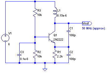
The core of any transmitter is typically an oscillator circuit, and in simple transmitters, such as QRSS devices, a crystal is often used. Frequency adjustment is achieved by modifying the capacitance to ground on one of the crystal's legs....
This low-power video transmitter is suitable for remote control applications, surveillance, or amateur radio. It employs seven transistors within a crystal oscillator multiplier RF power amplifier chain, along with a high-level video modulator. A supply voltage ranging from 9...
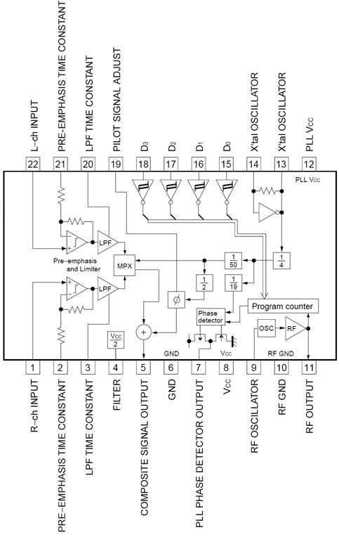
The BH1417 FM Transmitter architecture from RHOM is a compact solution that integrates multiple features into a single package. It includes pre-emphasis and a limiter to ensure that music is transmitted at the desired audio level, as well as...
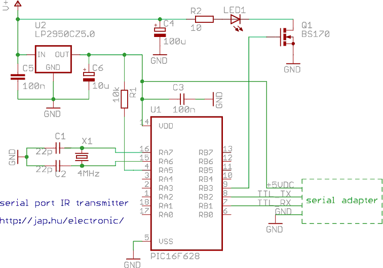
This is a programmable infrared (remote control) transmitter, which can be controlled from a PC serial port. It is capable of sending many remote control formats, including the Philips RC-5 standard. Exact formats with the timing parameter names are...
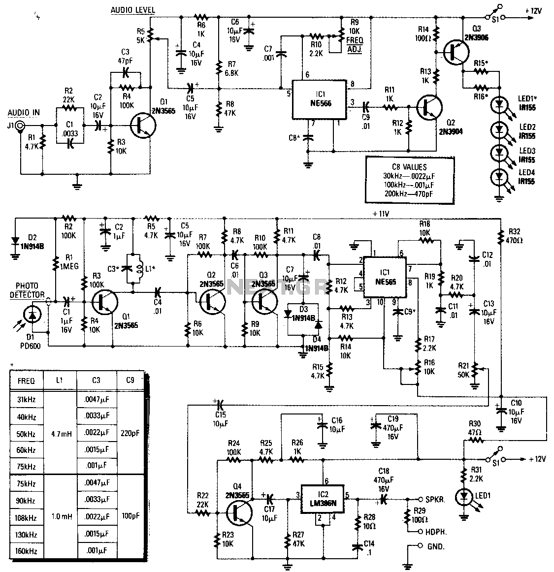
The infrared (IR) region is free from radio interference but can experience disruptions from incandescent lamps, fluorescent lamps, stray reflections, and other sources. A straightforward solution to this issue is to generate a carrier by modulating the IR radiation...
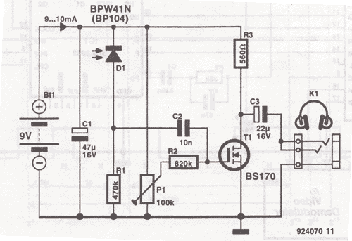
This wireless headphones transmitter ensures quality reception over a distance of 2 meters. The oscillator frequency ranges from 1750 kHz to 3500 kHz, and for the antenna, it... The wireless headphones transmitter operates within a frequency range of 1750 kHz...
Warning: include(partials/cookie-banner.php): Failed to open stream: Permission denied in /var/www/html/nextgr/view-circuit.php on line 713
Warning: include(): Failed opening 'partials/cookie-banner.php' for inclusion (include_path='.:/usr/share/php') in /var/www/html/nextgr/view-circuit.php on line 713