
Xbee doorbell project

The electronic circuit described involves an Arduino microcontroller, an XBee wireless module for communication, and a bell actuator. The circuit is designed to function as a code entry system where a user inputs a sequence of button presses that correspond to a randomly generated code.
The Arduino's setup function configures the necessary pins, including the bell and the buttons, and initializes serial communication. The bell is activated by setting pin 5 to HIGH, which triggers the bell sound. The loop function continuously monitors for serial input. When a specific character is detected, the bell is toggled on and off in a sequence, providing auditory feedback.
The buttons are managed using a Button library that allows for easy handling of button presses. Each button is set up with a pull-down resistor configuration to ensure stable readings. The uniquePress method is utilized to detect single presses of the buttons, allowing the system to capture the user's input accurately.
The pattern generation occurs in the pickPattern function, where a random sequence of button indices is created. These indices correspond to the buttons that will be lit up, providing a visual cue for the user. The system then waits for the user to replicate this pattern by pressing the buttons in the correct order.
Once the user has pressed the number of buttons equal to the length of the generated pattern, the checkCombo function is called to verify if the input matches the expected sequence. If the user's input is correct, the system signals success by lighting an indicator LED connected to pin 11 and sending a confirmation message via serial communication.
The reset function clears the captured button presses and prepares the system for a new round of input. The startMatching function manages the state of the button presses, ensuring that the system is ready to capture the user's input while providing feedback through the visual indicators.
Overall, this circuit effectively combines input handling, random pattern generation, and feedback mechanisms to create an interactive code entry system, demonstrating the capabilities of the Arduino platform along with wireless communication using XBee modules.When you press a start button, the arduino picks a random 4 diget code and flashes lights to show the code. When you repeat the code in the other buttons, the XBee will send a message to the other XBee, which will ring the bell.
int bell=5; void setup(){ pinMode(bell, OUTPUT); Serial. begin(9600); } void loop(){ if(Serial. available()>0){ if(Serial. read()=`D`) { for(int i=0;i<=6;i+){ digitalWrite(bell, HIGH); delay(20); digitalWrite(bell, LOW); delay(20); } Serial. print(`K`); } } } #include
print("pattern="); for(int i=0;i
available()>0){ if(Serial. read()=`K`){ reset(); } } } else{ digitalWrite(red, LOW); } } void reset(){ captureBtns=0; count=0; correct=false; digitalWrite(red, LOW); // previousMillis = millis(); } void startMatching(){ if(captureBtns
println(match[captureBtns]); captureBtns+; } 🔗 External reference
Related Circuits
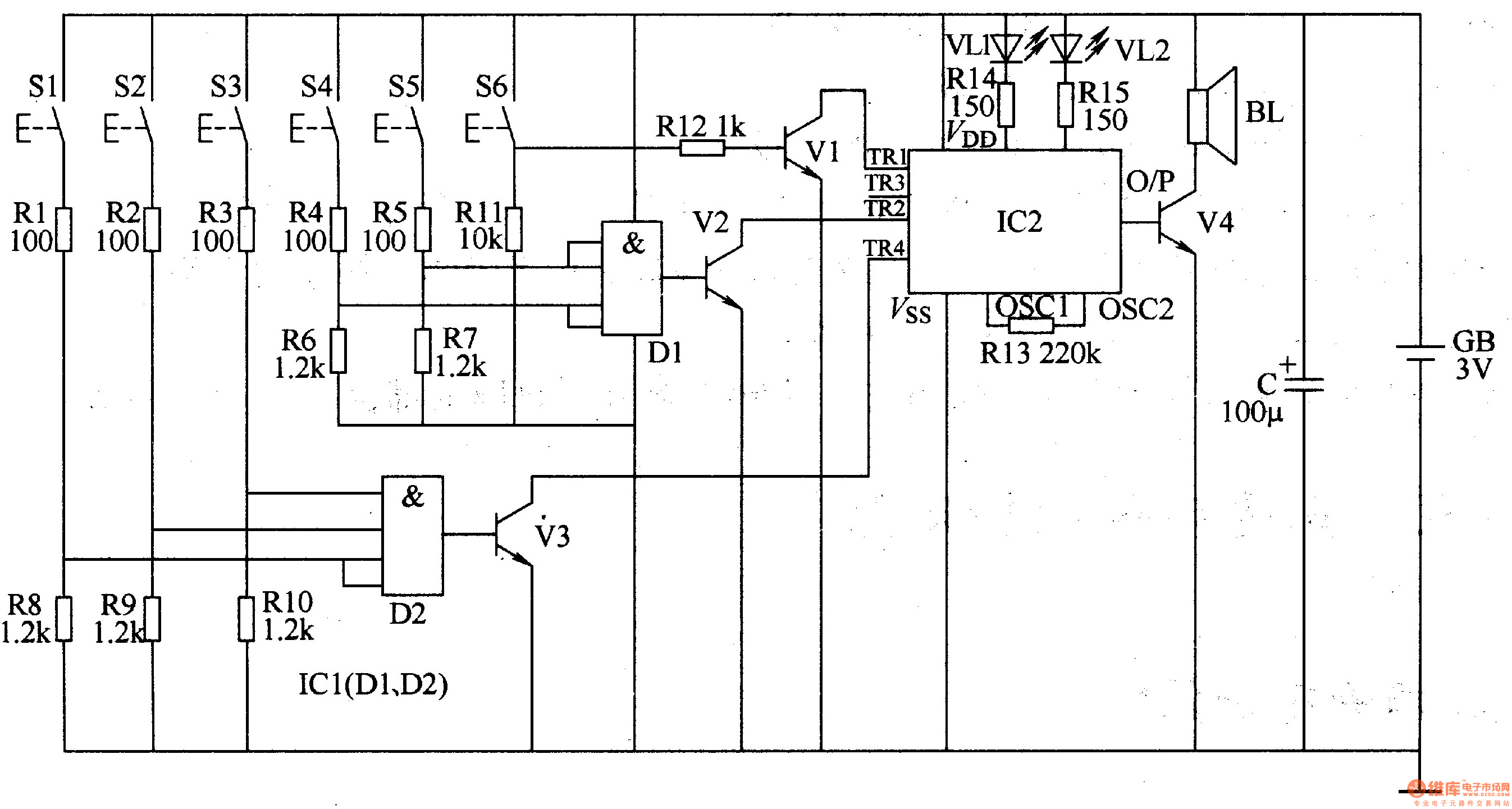
The three-tone electronic doorbell circuit includes a coding trigger circuit, a multi-tone generator, and an audio amplifier circuit, as illustrated in Figure 3-110. The coding trigger circuit is made up of buttons S1-S6, two four-input AND gates (D1, D2)...
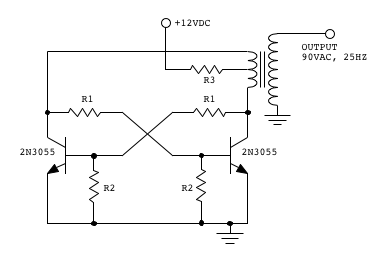
Make two telephones ring on stage. This involves sending a signal down a line to the phones. An old telephone exchange system was initially sought but not found. Several circuit ideas have been discovered, but the goal is to...
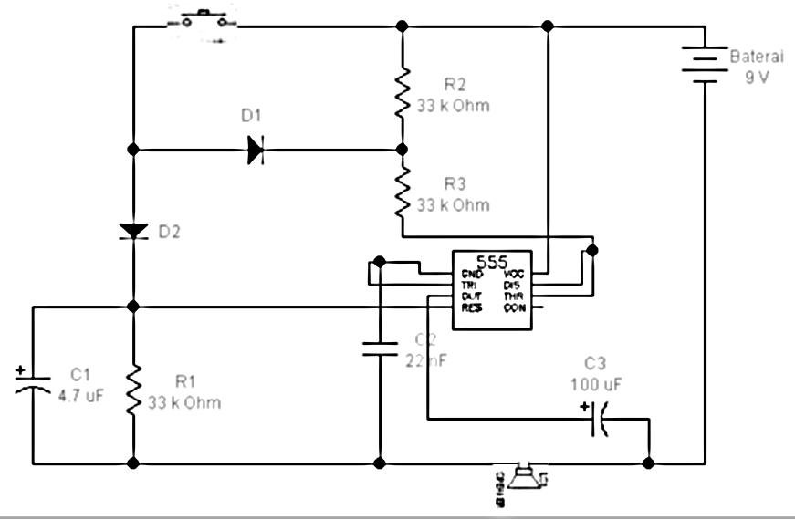
All components are arranged as depicted in the sequence below. Current will flow from the source voltage to the switch. When the switch is closed, current will flow through the diode, which acts as a closed switch due to...
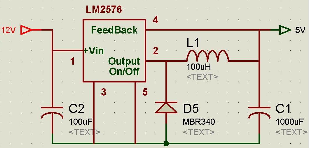
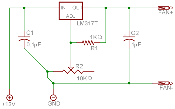
A regulated and noise-free power supply voltage is essential for microcontrollers and other components such as amplifiers, filters, and GPS devices. Voltage surges in the supply voltage can permanently damage embedded systems. A voltage regulator must maintain the output...
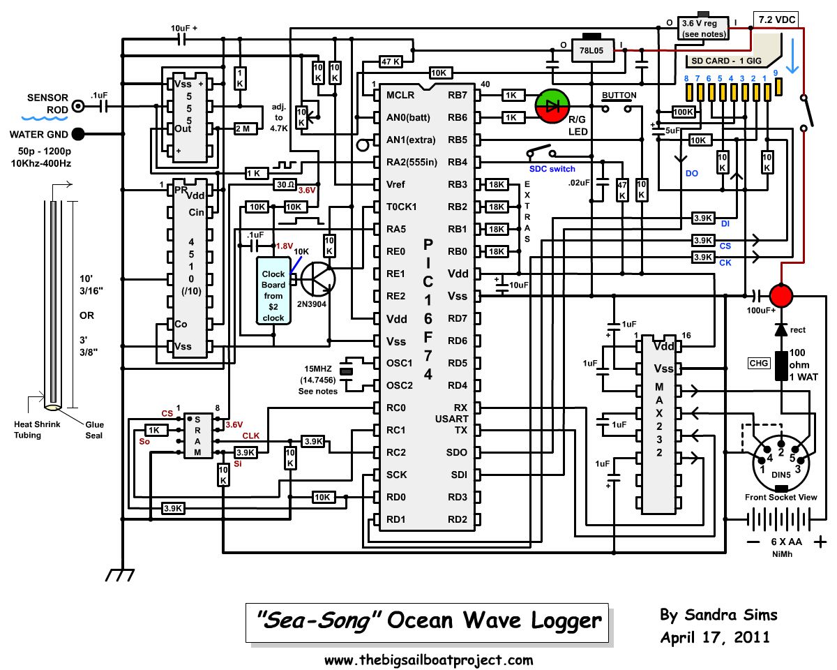
An idea emerged while observing the waves of Malaspina Strait during a storm a few weeks ago. The concept is to capture the sounds of ocean waves as an audio recording—not the typical sounds heard while walking on the...
This project was designed to introduce a friend to microcontrollers and circuits using various functionalities and spare parts. A PS2 numpad was utilized as the key entry mechanism, which was found at a thrift store and included the necessary...