
Three-tone electronic doorbell 2

The three-tone electronic doorbell circuit is designed to provide distinct audio notifications through a combination of various components. The core of the circuit is the coding trigger circuit, which is activated by pressing any of the six buttons (S1-S6). Each button corresponds to a different tone, allowing the user to select from three distinct sounds. The buttons are connected to two four-input AND gates (D1 and D2), which are part of the integrated circuit IC1. This arrangement ensures that the circuit only triggers when the correct combination of buttons is pressed, effectively coding the input signals.
Resistors R1 to R11 are strategically placed within the circuit to limit current and set appropriate voltage levels for the various components. The transistors Q1 to Q3 serve as switches that control the flow of current to the multi-tone generator, enhancing the circuit's functionality by enabling the amplification of the generated sounds.
The multi-tone generator circuit is responsible for producing the audible tones. It typically consists of oscillators and filters that create the desired sound frequencies. The output from this generator is then fed into an audio amplifier circuit, which boosts the sound level to ensure it can be heard clearly from a distance. The amplifier circuit may include additional components such as capacitors and inductors to enhance sound quality and stability.
Overall, this three-tone electronic doorbell circuit is a sophisticated assembly that combines coding, sound generation, and amplification to deliver a customizable and effective doorbell solution. The careful selection and arrangement of components ensure reliable operation and user satisfaction.The three-tone electronic doorbell circuit consists of the coding triggered circuit, multi-tone generator and audio amplifier circuit, and it is shown in Figure 3-110. Coding trigger circuit is composed of the buttons Sl-S6, two four-input AND gate (DI, D2) integrated circuit ICI, resistors Rl-Rll and transistors Vl-V3 and so on.
Multi-tone sound generator c.. 🔗 External reference
Related Circuits
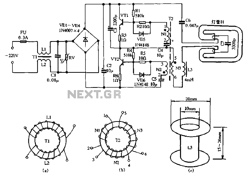
The circuit diagram illustrates a dedicated electronic ballast circuit for a 16W2D single-ended energy-saving lamp. The RFI filter circuit consists of components such as zinc oxide varistors for protection, bridge rectifiers, a high-frequency oscillator, and an LC series output...

This is a circuit design for a doorbell that produces a bird-like sound. The circuit is controlled by an NPN transistor. The operation of the circuit begins when P1 is set to an experimental value, starting with approximately 220...
The circuit is designed to operate with an audio power amplifier that uses 18V-0V-18V power rails. The specific voltage is not critical, but the feedback is referenced to an LED chain connected to a 12V rail, necessitating a separate...
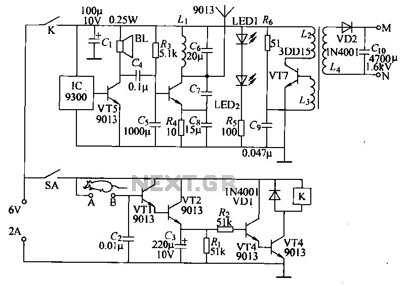
Power-saving electronic mousetrap. This example describes the minimal power consumption, which only occurs when a mouse enters the control zone during foraging activities. After a 30-second delay, the system enters a wait state, making it suitable for outdoor use....

Transistors Q1 and Q2 control latches Q3 and Q4 to switch on the lamp. A high resistance from touching the electrode biases Q1 or Q2 on, setting or resetting the latch. In this circuit, transistors Q1 and Q2 function as...
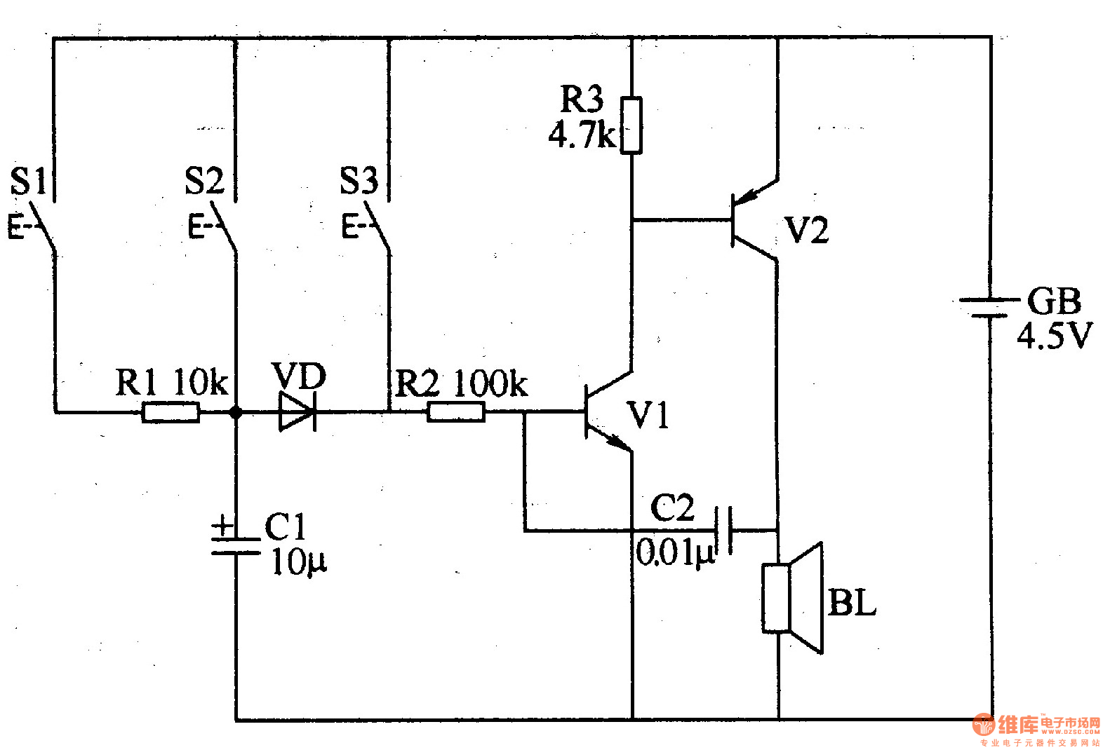
The three-tone electronic doorbell circuit includes buttons S1-S3, transistors V1 and V2, a speaker BL, resistors R1-R3, capacitors C1 and C2, a diode VD, and a battery GB, as illustrated in Figure 3-109. Resistors R1-R3 are 1/4W carbon film...