
XTR101 thermocouple input circuit diagram

The circuit operates effectively by employing a J-type thermocouple, which consists of two different metal wires joined at one end. This junction generates a voltage proportional to the temperature difference between the hot junction (where the temperature is measured) and the cold junction (where the compensation is applied). The cold junction compensation is crucial for accurate temperature readings, especially in environments where ambient temperature can fluctuate.
The semiconductor diode (D) serves as a reference point for the cold junction temperature. By maintaining the diode at a known temperature, the system can accurately adjust the output signal from the thermocouple. The voltage output from the thermocouple is linear within the specified temperature range, allowing for straightforward conversion to a corresponding current signal, which is typically used in industrial applications.
The output current varies with temperature, with 4 mA representing 0°C and scaling up to 20 mA at 1000°C. This current output can be utilized in various control systems or monitoring equipment, facilitating the integration of temperature measurements into broader electronic systems. The design ensures that the thermocouple's output is both reliable and precise, making it suitable for applications requiring high accuracy in temperature sensing. As shown in Fig having two temperature zones and thermocouple cold-junction compensation diode input circuit. This circuit uses the J-type thermocouple as a temperature sensor, a semiconductor diode D is formed as a relatively cold junction compensation 0oC measurements, measuring temperature, T1 in the range of 0 ~ 1000oC. Temperature T2 is equal to the temperature of the semiconductor diode D TD. When measuring the temperature at 0 ~ 1000oC change, J-type thermocouple will have 58mV change. At an ambient temperature of + 25, the typical value 1.28mV. Corresponding to 0oC transmission current 4mA, corresponding to the current transmission + 1000oC is 20mA.
Related Circuits
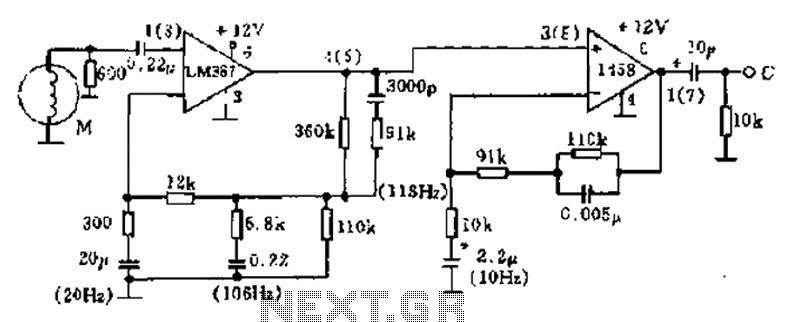
The phonograph pickup head is represented in the schematic as component M, which generates the pick-up signal and is processed through an LM387 amplifier circuit. The LM387 is part of the LM38X series, recognized for its advanced linear amplifier...
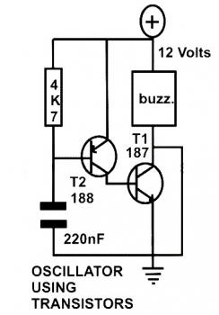
This schematic diagram represents a basic oscillator circuit utilizing two transistors. When the transistors and several passive components are connected as illustrated, the circuit begins to oscillate. The oscillation frequency can be modified by altering the values of either...
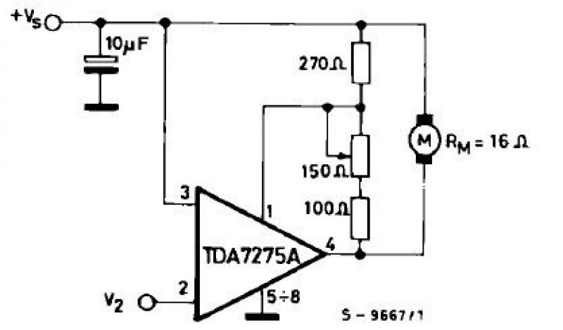
The TDA7275A linear integrated circuit, housed in a minidip plastic package, can be utilized to design a straightforward speed regulator electronic project suitable for regulating the speed of small DC motors. The TDA7275A DC speed controller project is specifically...
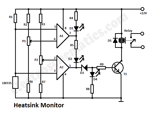
This heatsink temperature monitor circuit uses three LEDs to signal when the temperature exceeds two boundary levels. When the heatsink temperature is below 50 degrees... This heatsink temperature monitor circuit is designed to provide visual indications of temperature levels using...
Mobile phone chargers available in the market are quite expensive. The circuit presented here serves as a low-cost alternative to charge mobile telephones or battery packs with a rating of 7.2 volts. The proposed circuit design utilizes a straightforward approach to...
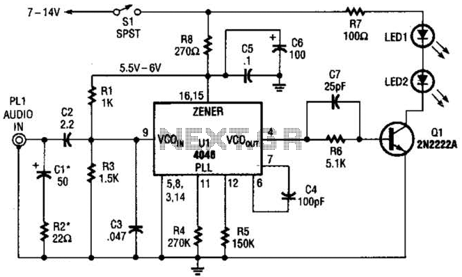
The transmitter for the wireless headphones is constructed using a CD4046 CMOS phase-locked loop, which is paired with a driver transistor and a set of infrared LEDs. While the CD4046 contains two phase comparators, a voltage-controlled oscillator (VCO), a...