
Phonograph amplifier circuit diagram
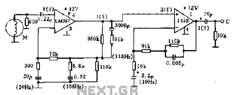
The phonograph pickup head serves as the initial transducer in the audio signal chain, converting mechanical vibrations from the vinyl record into an electrical signal. This signal is typically weak and requires amplification to be usable for further processing. The LM387 amplifier circuit is specifically designed to enhance the quality of this signal while minimizing noise and distortion, which is critical for high-fidelity audio reproduction.
The LM387 amplifier is notable for its low noise operation, which is essential in audio applications to prevent unwanted hiss or background noise from interfering with the desired sound. Its low distortion characteristics ensure that the output signal closely resembles the original input, preserving the integrity of the audio signal. The wide bandwidth capability allows the amplifier to handle a broad range of audio frequencies, making it suitable for various audio applications, including high-fidelity sound systems.
The use of a single power supply simplifies the design and reduces the complexity of the circuit, making it easier to implement in various audio devices. Internal compensation helps to stabilize the amplifier's performance over a range of operating conditions, while power supply decoupling reduces the impact of power supply variations on the amplifier's output.
The 600-ohm resistor connected in parallel with the current flow serves a dual purpose. It helps to limit the current to a safe level, protecting the amplifier from potential damage due to excessive current, while also acting as a load that optimizes the performance of the pickup head. This configuration ensures that the system operates efficiently, providing high-quality audio output while maintaining reliability and longevity.
Overall, this circuit exemplifies the integration of advanced amplifier technology with traditional audio components, resulting in a high-performance solution for vinyl playback systems. As shown in FIG phonograph pickup head M from the pick-up signal and l458 through LM387 amplifier circuit. LM387 is LM38X series one. LM38X series are highly advanced linear am plifier IC, with low noise, low distortion, wide-band and curb the beat and so on. In addition, a single power supply, internal compensation, power supply decoupling and regulation, large output voltage change and larger power broadband, but also its features. Figure and pickup head 600 ohm resistor in parallel with the current F to stopping.
Related Circuits

This circuit delivers an initial voltage of 2.5V per cell to rapidly charge a car battery. The charging current decreases as the battery charges. This circuit is designed to provide an efficient charging solution for car batteries by applying an...
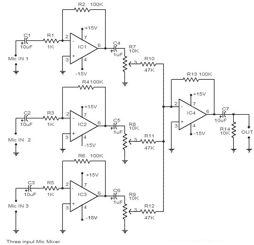
This is a circuit diagram of a 741 IC-based three-input microphone mixer circuit. A total of four 741 ICs are utilized, with IC1, IC2, and IC3 serving specific functions within the design. The circuit utilizes four operational amplifiers from the...
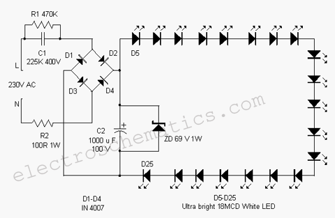
This white LED light illuminates the porch with cool white light. The circuit features a simple and energy-saving design. Its current consumption is practical. The white LED light circuit is designed to provide efficient illumination while minimizing energy usage. The...
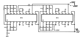
Later, there will be applications including a Basic Circuit Description, Block Diagram of the MF10, Programmable Dual Clock Generator, Butterworth Lowpass Filter, MF10 as an Input Filter and Sample/Hold, Generating Quadrature Sine Waves, and the Non-Inverting Integrator used in...
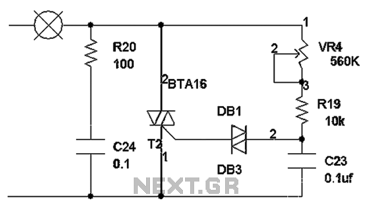
The TRIAC dimmer circuit diagram operates on the principle that a 220V lamp is controlled through the charging of capacitor C23 via resistors VR4 and R19. The charging time is influenced by the values of VR4 and R19, where...
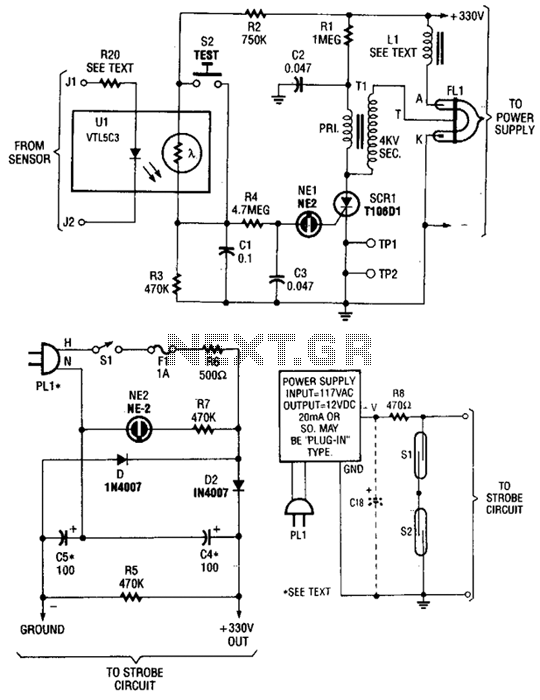
The circuit is activated by an LED/photoresistor isolator (U1), which combines a light-dependent resistor (LDR) and an LED in a single package. This device was selected for its high isolation characteristic of 2000 V, which is essential since the...
Warning: include(partials/cookie-banner.php): Failed to open stream: Permission denied in /var/www/html/nextgr/view-circuit.php on line 713
Warning: include(): Failed opening 'partials/cookie-banner.php' for inclusion (include_path='.:/usr/share/php') in /var/www/html/nextgr/view-circuit.php on line 713