
XTR108 voltage excitation bridge circuit diagram

The XTR108 is a precision current loop transmitter designed for use in applications that require the measurement of resistance temperature detectors (RTDs). In this context, the bridge circuit is a critical component that allows for the accurate measurement of temperature by converting the resistance changes of the RTD into a corresponding voltage signal.
The excitation voltage (VEX) provided to the bridge is crucial for maintaining linearity in the output. The relationship VEX = 2IREFR1 indicates that the excitation voltage is twice the product of the reference current (IREF) and the resistance (R1) used in the circuit. This configuration helps to ensure that the output voltage remains proportional to the temperature changes detected by the RTD.
The linearization algorithms applied in this circuit are essential for correcting any non-linearities that may arise from the RTD's response characteristics. By adjusting the excitation voltage and employing these algorithms, the system can achieve a more accurate and stable output, which is particularly important in precision temperature measurement applications.
In summary, the XTR108 bridge circuit effectively utilizes a linearized approach to provide a stable excitation voltage, ensuring that the RTD's resistance changes correspond accurately to temperature variations. This method enhances the reliability and precision of temperature readings in various industrial and scientific applications. As shown for the bridge circuit excitation voltage XTR108. Circuit for the bridge excitation voltage is linearized adjusted, linearized algorithms that RTD linearization same r esponse. Excitation voltage VEX 2IREFR1, where VEX is the excitation voltage at both ends of the bridge.
Related Circuits
The metal detector circuit is shown here that the limits represent the sake of simplicity for a metal detector, but the design works remarkably well. It only uses 40,106 Hex Schmitt inverter IC, a capacitor and a search coil...

This is a highly sensitive envelope detector designed for AM radio applications. The circuit, illustrated in Figure 1, enables linear detection of weak signals with a modulation depth of 80-85%. The first stage (VT1) functions as a common-emitter amplifier...
Features: 1. The operating voltage is low, functioning with a single supply of 2.0V. 2. Power consumption is minimal, with a supply current of 5 µA at 32 kHz and 130 µA at 1 MHz. 3. It has a...
This is a compact, easy-to-build amplifier that utilizes a single integrated circuit (IC) to deliver 40 watts of audio power. It is well-suited for amplifying audio signals from devices such as mobile CD players or iPods. The integrated circuit...

The circuit employs a field-effect transistor (FET) at the input of a Schmitt trigger, allowing the use of a low-value capacitor. The trigger, controlled by Q1 and O2, exhibits a hysteresis of approximately 3V, regulated by a 3V zener...
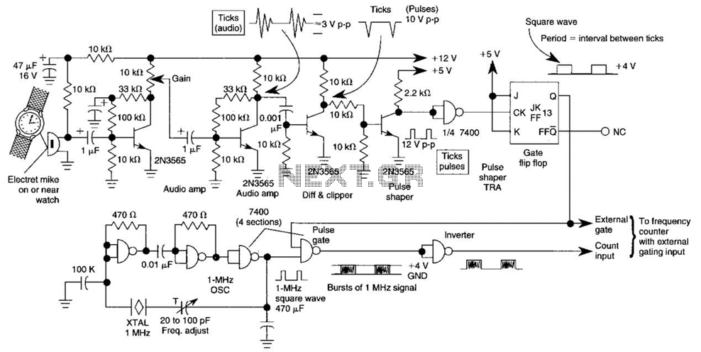
This circuit adapts a frequency counter to measure intervals. It was originally utilized as a shutter speed checker for photographic applications. The watch ticks are clipped, shaped, and formed into a square wave. This square wave is employed to...