
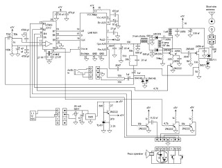
Sensitive envelope detector circuit diagram

The envelope detector circuit described employs two transistors to achieve effective AM signal demodulation. The first stage, VT1, is configured as a common-emitter amplifier, which amplifies the incoming AM signal. This stage is critical for enhancing weak signals, allowing for better detection of the envelope of the modulated waveform. The common-emitter configuration is known for providing significant voltage gain, which is essential when dealing with low-level AM signals.
Following the amplification stage, the second transistor, VT2, is configured as an emitter-follower. This configuration is characterized by its high input impedance and low output impedance, which effectively isolates the first stage from the load. The low current operation of VT2, facilitated by the high resistance of resistor R5, is crucial in minimizing power consumption while maintaining performance. This low current operation also helps to reduce thermal noise, further enhancing the sensitivity of the envelope detector.
The demodulation process occurs at the lower bend of the volt-ampere curve, a region that allows for optimal linearity in signal processing. The deep negative feedback employed in the emitter-follower stage significantly contributes to the high linearity of the demodulated output. This feedback mechanism helps to stabilize the gain and improve the overall fidelity of the detected audio signal.
In summary, this envelope detector circuit leverages the strengths of both common-emitter and emitter-follower configurations to achieve precise AM signal demodulation, making it suitable for applications requiring high sensitivity and linear detection of modulated signals.This is a very sensitive envelope detector for AM radio. The circuit (see Fig. 1) provides linear detection of weak signals with modulation depth of 80. 85% The first stage (VT1) is a common-emitter amplifier circuit for input signals, the second stage is an emitter-follower circuit (VT2). The transistor VT2 operates at low current because of the hi gh resistance of the resistor R5. The process of AM demodulation occurs at the lower bend of the volt-ampere curve. A high linearity of demodulation provided by the deep negative feedback in the emitter-follower circuit. 🔗 External reference
Related Circuits

This circuit was originally designed to detect weak flashes of laser light reflected off a fabric video projection screen. It was used as part of a firearm training system. It generates a 100 ms output pulse whenever it detects...
The common characteristic of all previous low-power FM transmitters built over the decades is that their operating frequency is determined by an LC resonant circuit. Some of these transmitters exhibited excellent stability, while others did not; however, there has...
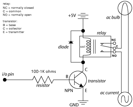
The schematic illustrates the Relay Wiring Circuit Diagram used to control an air conditioner or other high-current devices via a microcontroller. The relay wiring circuit serves as an interface between low-voltage microcontroller signals and high-voltage appliances, such as air conditioners....

This circuit for a laser door alarm operates on the principle of laser beam interruption. A low-cost laser pointer serves as the light source. When an object disrupts the laser beam, an alarm is triggered for a few seconds....
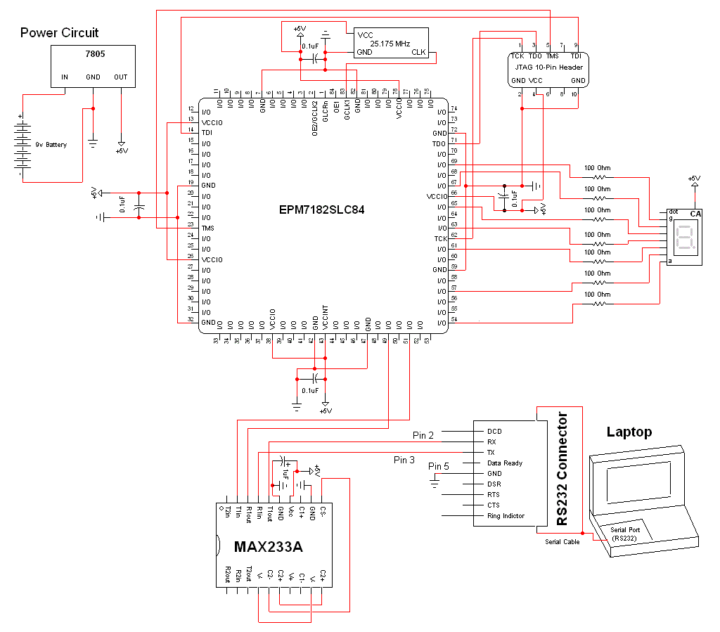
The schematic for this project is a modified version of the CPLD development board schematic. Several new components have been added for this project, and the completed schematic can be viewed below. The main components in the schematic are...
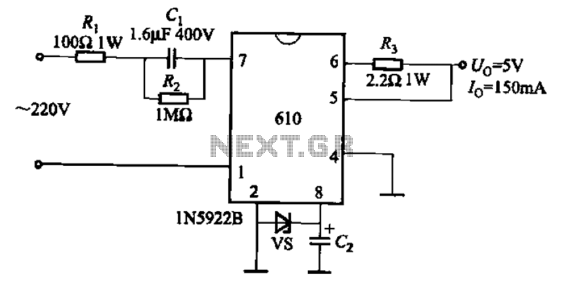
The AX610 Series has a maximum output current of 100 mA and features a scalable output current with an access regulator. The configuration includes two reverse polarity series regulators (2CW106, U: approximately 8.2V) as depicted in Figure (a). Figure...