
XTR110 Voltage-Current Converter

The XTR110 is a precision current transmitter designed for industrial applications, capable of converting a low-level input signal into a proportional current output. In scenarios where the output current exceeds 40mA, it becomes necessary to modify the internal resistance to accommodate higher current levels. The internal resistance, R9, which is fixed at 50Ω, limits the maximum output current. By replacing R9 with an external resistor, REXT, the circuit can be adjusted to handle higher currents without compromising the performance of the XTR110.
To determine the appropriate value for REXT, the ratio of the original span to the required span must be calculated. The original span is defined as the maximum output current the device is designed to produce under normal conditions, while the required span is the new maximum output current desired for the application. For example, if the original span is 20mA and the required span is 10A, the calculation would be as follows:
REXT = 50Ω × (20mA / 10A)
This calculation effectively scales the internal resistance to match the new output requirements. It is critical to ensure that REXT is connected properly between pins 13 and 16 to maintain the integrity of the circuit. Additionally, care should be taken to select a resistor that can handle the power dissipation associated with the higher output current.
In summary, by replacing the internal resistance R9 with an appropriate external resistor REXT, the XTR110 can be effectively configured to output higher currents, thus enhancing its versatility for various industrial applications. Proper calculation and implementation of this modification are essential for achieving the desired performance without damaging the device.As shown in the picture, when the output current exceeds 40mA the internal resistance 50? in the XTR110 (R9) should be replaced by external resistance REXT. REXT is connected between the 13 foot and 16 foot. REXY=R9(original span/required span). For example, the XTR110 in the picture`s original span is 20mA and now the required span is 10A. If R9=50?, then.. 🔗 External reference
Related Circuits
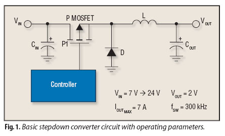
Although step-down converters, commonly known as buck converters, are highly popular, the guidelines and calculations that facilitate their design can be challenging to locate. Buck converters are a type of DC-DC converter that efficiently reduce a higher input voltage to...
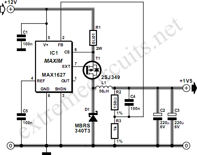
Most small internal combustion engines used in model building utilize glow plugs for starting. However, glow plugs operate at 1.5 V, while components like fuel pumps, starter motors, and chargers typically operate at 12 V. This discrepancy necessitates a...
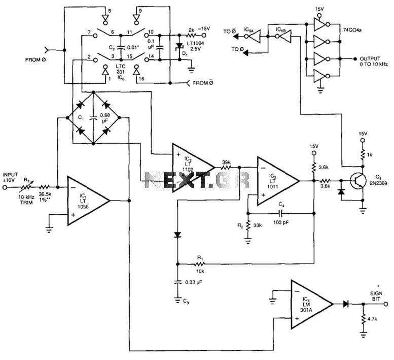
This voltage-to-frequency converter (VFC) accepts bipolar AC inputs. For -10 to +10 V inputs, the converter produces a proportional 0 to 10 kHz output. Linearity is 0.04%, and the temperature coefficient (TC) is approximately 50 ppm/°C. To understand the...

The pressure transmitter circuit data acquisition system utilizes the 1B31, an 18-bit A/D converter (AD1170), and an MCS-51 microcontroller. The configuration, as depicted in the accompanying diagram, features a full-scale output voltage of 10 mV from the pressure transmitter...
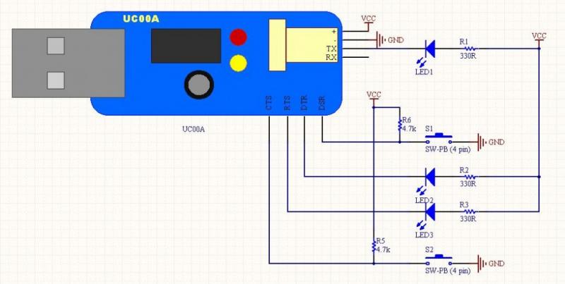
The LEDs operate in an active-low configuration (0), while the initial state of the switches is high (1). In other words, the PC software must send a low signal (0) to activate the LEDs, and if a low signal...
The basic analog to digital (A/D) converter circuit has been previously explained. In addition to this, various types of monolithic analog to digital converters exist, including the integrating A/D, integrating A/D with three-stage outputs, and the tracking A/D with...