
xx Band Audio Equaliser

A 20-band equalizer (EQ) is designed to allow precise control over the frequency response of audio signals, particularly in high-power applications such as a 900-watt MOSFET power amplifier. The equalizer achieves this by dividing the audio spectrum into 20 discrete frequency bands, each of which can be adjusted independently to enhance or attenuate specific frequencies.
The operational principle of the EQ involves using band-pass filters for each frequency band. Each filter section typically comprises resistors, capacitors, and operational amplifiers (op-amps) configured to define the center frequency and bandwidth of the filter. The output level of the EQ is influenced by the resistors used in the circuit; specifically, when two equal resistors are employed, the gain can be set to 3, which means the output signal will be amplified to three times the input signal level, compensating for any losses incurred through the filtering process.
In the schematic, the filter sections are critical components that determine the EQ's performance. Each filter section can be constructed using a combination of passive components (resistors and capacitors) and active components (op-amps) to shape the frequency response. The design allows for flexibility; additional filter sections can be added to increase the number of frequency bands, thereby enhancing the equalization capabilities of the amplifier.
To clarify the filter section's role, it is essential to understand that each filter is tuned to a specific frequency. The selection of resistor and capacitor values dictates the cutoff frequencies and the gain characteristics of the filter. In essence, the filter section is responsible for isolating and adjusting the amplitude of a designated frequency band, which contributes to the overall sound shaping offered by the EQ.
In conclusion, the design and implementation of a 20-band EQ for a high-power amplifier involve careful consideration of filter sections, gain settings, and the interaction between components to achieve the desired audio output. The ability to manipulate multiple frequency bands allows for a tailored audio experience, making it a valuable addition to any high-performance audio system.A 20 Band EQ for my 900Watt MOSFET Power Amplifier. The Output Level would drop by the Ammount of resistors, so for 2 Equal Resistors, I should amplify it by a gainof 3. Would that propably work Eek, that is very confusing. The first schematic is a simple EQ and the text says, you can add as many bands as you want, by adding filter sections.
But I don`t realy get, what part of the whole Circuit is the Filter section. 🔗 External reference
Related Circuits

An audio filter is positioned at the input of each audio integrated circuit (IC) chip to filter the audio signal intended for speakers. A low-pass filter is utilized for the woofer, while a high-pass filter is employed for midrange...
Here is the schematic for an 8 watt audio amp. This amp can be used as a simple booster, the heart of a more complicated amplifier or used as a guitar amp. The circuit can be built on a...
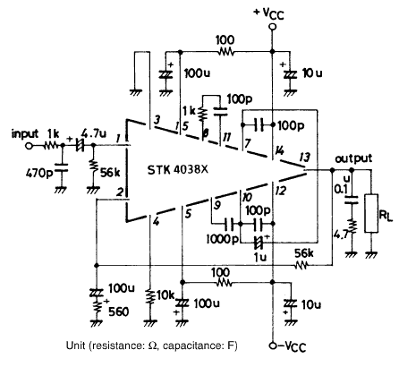
Using the STK4038X audio amplifier IC, can be designed a very simple high power and efficiency audio power amplifier. This circuit is manufactured by Sanyo Corporation and will provide an output power of 60 watts on an 8 ohms...
.gif)
This circuit utilizes a single integrated circuit (IC) along with a minimal number of external components to display audio levels through ten LEDs. The input voltage range is from 12V to 20V, with a recommendation for 12V. The LM3915...
Audio Light Modulator. Audio light modulation enhances the enjoyment of music during events held at home or outdoors. Presented here is a straightforward circuit for this purpose. The audio light modulator circuit is designed to synchronize light effects with audio...
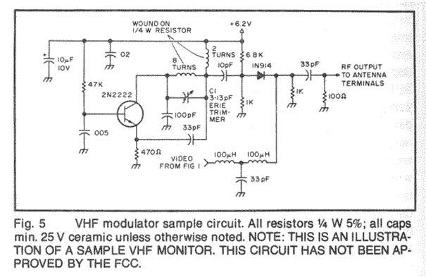
The project involves designing and constructing a wireless transmitter that operates on FM frequencies, enabling the transmission of video and audio signals over a specified distance to an FM tuner. This development addresses the growing demand for portability and...