
Wireless Piezo Beeper


The design of the wireless audio transmission system involves several key components and considerations. The 433MHz wireless modules serve as the core of the system, facilitating the transmission and reception of audio signals. The transmitter module captures the audio output from the vario, modulating it onto a radio frequency signal. This modulation process is critical for ensuring that the audio can be transmitted over the airwaves without degradation.
In the receiver circuit, the demodulation process takes place, converting the received radio frequency signal back into an audio signal that can be played through the piezo speaker. The choice of components, including the piezo speaker, is essential for achieving clear audio reproduction. The placement of the piezo speaker is also crucial; it should be positioned to ensure optimal sound delivery while maintaining comfort for the user.
Power management is another vital aspect of the design. The transmitter's low power consumption allows it to draw from the vario's power supply without significantly impacting battery life. Careful attention must be paid to the selection of power connection points on the vario's PCB to ensure that the transmitter is powered down when the vario is off. This feature is important for preventing unnecessary battery drain.
The enclosure design, utilizing a modified 2xAAA battery holder, provides a compact and practical solution for housing the circuit. The integration of the receiver into a helmet or harness is facilitated by the flexible mounting options, ensuring that the user can comfortably wear the system during use.
Overall, this wireless audio transmission system is designed to enhance the functionality of the vario by providing a convenient and efficient means of audio output, thereby improving the user experience in various applications, such as aviation or other outdoor activities.The design is based around a pair of 433MHz wireless modules. These can be bought pre-built and contain all of the radio frequency components that we need. We use these modules in our two circuits; one to transmit our vario audio and the other to receive and reproduce it. It is worth building the receiver first because it can be used to test the
transmitter circuit. The receiver circuit receives the radio signal and demodulates it into something resembling our vario`s audio signal. This is used to drive the receiver`s own piezo which is located closer to our ear than the vario is. The schematic is shown below. When the battery power is on and there is no transmitter operating nearby, the piezo should produce some audible noise.
This is a simple way to test that the receiver is working. Also, when we turn our vario off, the noise reminds us that the receiver battery needs to be turned off too. Veroboard can be used to connect the various components. The layout which I use is shown here. I use a modified 2xAAA battery holder as an enclosure for the circuit and glued it to the back of a 9V battery holder as shown in this photo.
Some helmets like the Icaro 4-fight have tail compartments which are ideal for mounting the receiver. In this situation the piezo can be mounted on the receiver`s enclosure. It should not be located adjacent to an ear or it will be too loud. The battery switch can be installed somewhere accessible on the helmet. If there is no suitable place on your helmet it is possible to mount the receiver somewhere in your harness.
The piezo can be placed on longer leads if necessary so that it can be placed near your head. It should be possible to hear the piezo if it is placed on the shoulder straps. This circuit takes our vario audio signal and modulates it onto the radio frequency signal which is transmitted through an antenna. The schematic is shown below. The transmitter takes power directly from the vario`s own printed circuit board so that we don`t end up with yet another battery to maintain.
The power consumed by the transmitter is modest compared with the power consumed by the vario itself so you shouldn`t notice the vario battery going flat much faster than before. In fact you will be able to turn the vario volume to it`s lowest setting once the wireless system is working which will save some vario power.
The transmitter circuit should draw less than 10mA from the vario. Suitable points need to be chosen on your vario PCB for the +BATT and 0V supply connections. The TXC1 wireless transmitter module requires a 3V power supply. Some varios have 3V batteries so it is a very simple matter to obtain a supply. For these varios you should omit diode D1 from the transmitter circuit. An example is when installing the transmitter in a Brauniger IQ Competition GPS which has 2xAA main cells and 2xAAA reserve cells. Some other varios use different battery technologies which operate at voltages other than 3V. A suitable supply rail needs to be found on the vario PCB for the power connections. If a 3. 6V supply rail can be found, diode D1 should be included in the circuit so as to drop our transmitter voltage to the required 3V.
An example is when installing the transmitter in a Brauniger Compeo (aka Galileo) which has a suitable 3. 6V supply rail. If your vario doesn`t have a battery or supply rail of either 3V or 3. 6V, you won`t be able to use this design as is. You will need a 3V voltage regulator built into your circuit, or the transmitter will need it`s own battery.
Make sure that the supply connection points are chosen so that the transmitter is powered down when the vario is turned off, otherwise you will flatten your vario battery between flights. The AUDIO signal needs to be taken from a part of the PCB that drives the vario`s piezo buzzer. Don`t permanently disconnect the vario`s piezo in order to do this. After all you may still need it one day if
Related Circuits
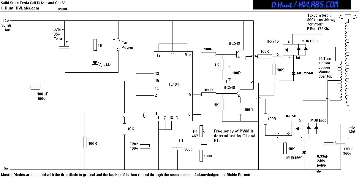
This is a solid-state version of a Tesla coil, replacing the spark gap with MOSFET transistors and utilizing a close-coupled primary coil without capacitors. The method of driving the primary coil varies among designs. After researching various works online,...
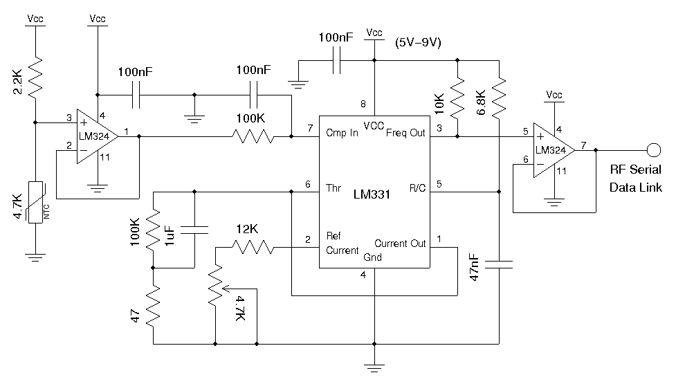
A voltage-to-frequency conversion chip can be utilized in conjunction with an analog temperature sensor, such as the LM335 or a thermistor, to transmit the modulated frequency signal via an RF data link module. Alternatively, a digital temperature sensor can...
This circuit is designed for alerting purposes after a specified time has elapsed. It is suitable for tabletop games that require a fixed duration to answer a question or to move a piece. In this context, it serves as...
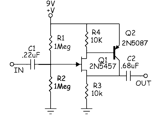
This is an affordable buffer circuit designed for mixing passive pickups with EMG active pickups, or for buffering piezo pickups to be combined with magnetic pickups. The frequency response of the circuit is nearly flat, and the noise level...
This article demonstrates that enhancement mode GaN transistors facilitate substantial efficiency enhancements in resonant topologies and provides a practical example of wireless power transmission. Enhancement mode Gallium Nitride (GaN) transistors are semiconductor devices that have gained attention for their ability...
By combining a current-reuse amplifier and a switch-based mixer, a dual-band receiver front end offers excellent performance with extremely low power consumption. The dual-band receiver front end integrates a current-reuse amplifier and a switch-based mixer to achieve high performance while...