
Z-80 Bus Monitor/Debugger

This circuit serves as a vital tool for debugging and verifying the functionality of microprocessor designs, particularly in the early stages of development when both hardware and software may be untested. The inclusion of a 5-byte hexadecimal display allows for real-time visualization of the data bus, which is crucial for understanding the behavior of the microprocessor during operation. The use of a comparator to set trigger conditions enhances the circuit's flexibility, enabling users to focus on specific events in the program execution.
The 40-pin IC test clip ensures a secure and reliable connection to the microprocessor, facilitating the acquisition of necessary signals without requiring extensive modifications to the existing hardware setup. This feature is particularly beneficial in prototyping environments where rapid iterations are common. By allowing the user to set trigger conditions, the circuit can be tailored to capture specific data transactions of interest, making it a versatile tool for a range of debugging scenarios.
Moreover, the adaptability of the circuit to various microprocessors and bus widths increases its utility across different platforms and applications. This capability is essential for engineers working with diverse microcontroller architectures, as it allows for consistent debugging methodologies regardless of the specific hardware being utilized.
In summary, this circuit not only simplifies the process of tracing program execution but also enhances the overall debugging experience by providing clear visibility into the operation of microprocessor designs. Its straightforward design, coupled with the ability to adapt to different architectures, makes it an indispensable resource for electronics engineers engaged in microprocessor development and testing. Getting microprocessor designs to work is notoriously difficult when both the software and hardware are new. The usual approach is to run test routines that address memory and I/O, but do not rely on their correct functioning. However, miswiring in any part of the circuit usually leads to a misleading jumble of signals that might require a logic analyzer to interpret.
This simple circuit will trace the program execution and help point to the problems. Although the circuit shows connections for a Z-80, the circuit can very easily be adapted for any 8-bit microprocessor or with additional circuitry for CPUs of any bus width. The circuit consists of a 5-byte hexadecimal display and comparator, which are wired to a 40-pin IC test clip.
The test clip sits over the microprocessor (in this case a Z-80), where it gets power and all the required signals. The address bus and control lines are fed to the comparator, where (by means of switches) a trigger condition can be set.
Following the trigger, the next 5 occurrences of either RD or WR will latch the contents of the data bus into the 5 hex displays, each in turn. For example, select address 0000 Ml Rd and reset the CPU. The displays will show the very first instruction fetch, followed by its data and any consequent action.
Even details, such as stack writes and subroutine addresses, are included. To trace longer portions of a program the address switches can be incremented to follow the execution path.
Related Circuits
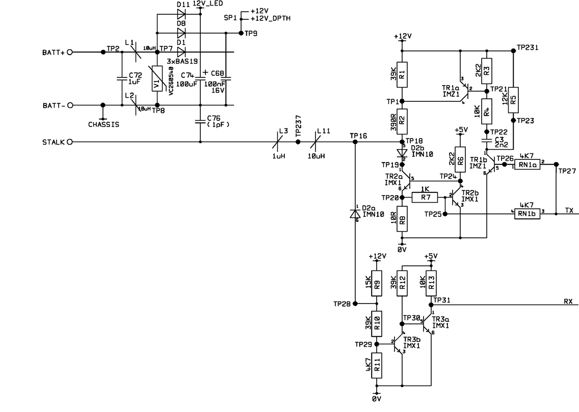
A project involves using a PIC microcontroller to communicate with the Raymarine SeaTalk bus. The schematic diagram for a Raymarine instrument shows a logic chip connected to the TX and RX connections on the right side, while the SeaTalk...

When discussing fan control, there are generally two methods: linear control and pulse-width modulation (PWM) control. Linear control is the most commonly used method, which involves reducing the voltage supplied to the fan. For a fan rated at 12...

Field bus technology and intelligent instrument technology are currently two of the most rapidly evolving technologies in automation and control. In the realm of field bus technology, the CAN bus has established itself as a relatively fast communication standard...
This is the most simple phone busy indicator is possible with only three parts. Connect the circuit so that the green light illuminates when the line is free. If the receiver than the hook, the green LED light is...
Have you ever been using the modem or fax and someone else picks up the phone, breaking the connection? Well, this simple circuit should put an end to that. It signals that the phone is in use by lighting...
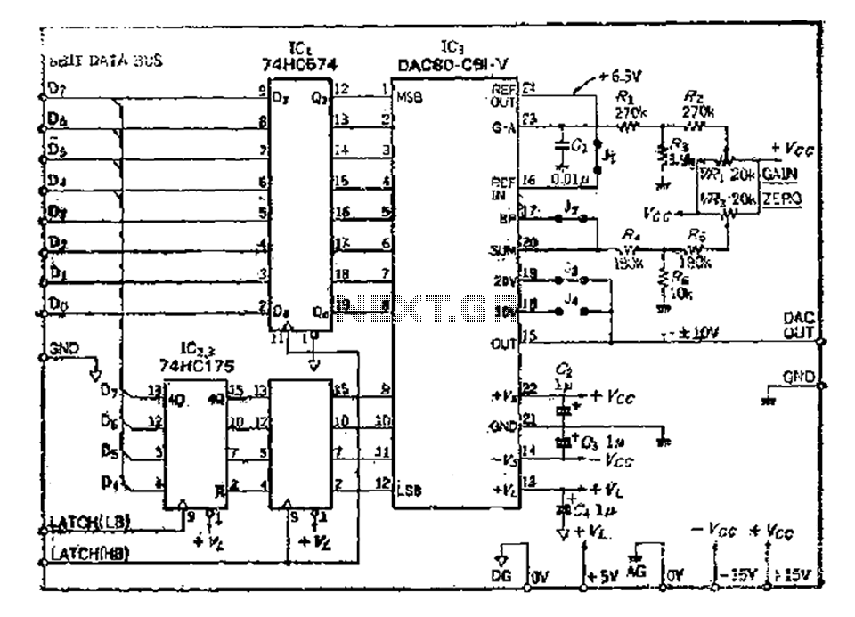
The 8 microcomputer data operates with an 8-bit parallel output, while also accommodating serial input for D-A converters. Typically, data must be entered in two groups and processed as a whole. The requirements for data latching involve 16 straight...